
Testing and Inspection of Idle Speed/Throttle Actuator Component
3. Measure the resistance between terminals (5) and (6) or between terminals (5) and (4) of the idle speed control servo connector.
Standard resistance: 28 - 33 Ohms [at 20°C (68°F)]
Operation Check
1. Remove the throttle body.
2. Remove the stepper motor.
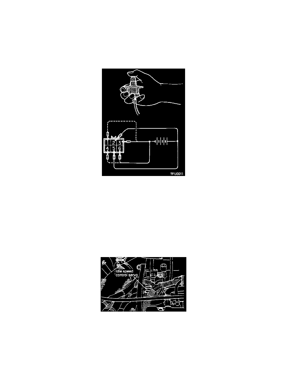
3. Apply voltage as indicated below and check for presence/ absence of vibration due to stepper motor operation.
a. Connect the positive terminal of the power supply (about 6V) to terminals (2) and (5) of the connector.
b. Connect the negative terminal of the power supply to terminals (3) and (6).
c. Connect the negative terminal to terminals (1) and (6).
d. Connect the negative terminal to terminals (1) and (4).
e. Connect the negative terminal to terminals (3) and (4).
f.
Connect the negative terminal to terminals (3) and (6).
g. Connect the terminals in sequence from step 6 to 2.
4. If vibration is felt as a result of the inspections, the stepper motor can be judged as normal.
Idle Air Control (IAC) Motor
1. Verify that the Idle Speed Control Servo stepper motor is operating by listening for sound when the ignition switch is turned to the ON position
(without cranking the engine).
2. If the Idle Speed Control Servo does not make an audible sound, the possible cause may be the stepper motor actuation circuit, electrical
connections, the Control Module, or the stepper motor itself.