
Laser FWD L4-1997cc 2.0L DOHC Turbo (1993)
3. If the volume air flow sensor output frequency is high, the engine resistance may increase or the compressed pressure may leak.
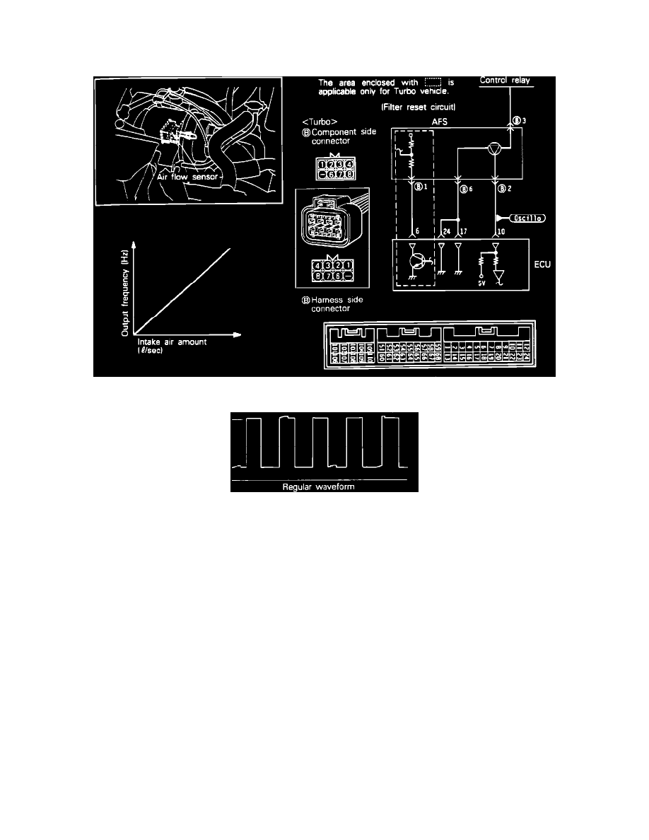
4. If a wire is broken in the filter reset circuit of a turbo vehicle, shock may be felt during deceleration from high speed (high load) operation.
Sensor Testing
Air Flow Sensor Circuit
Scope Pattern
Note: To test the Air Flow Sensor, located inside the air cleaner housing proceed as follows.
OSCILLOSCOPE TESTING PROCEDURES:
1. Run engine at idle speed.
2. Engine coolant temperature should be at: 85-95°C (185-205°F), with no electrical accessory loads on.
3. Connect the input probe of the oscilloscope, to the pickup point shown in the circuit diagram, and check the wave form.
-
If scope pattern is not as depicted in image, continue with the rest of the test procedures before replacing the assembly.
FREQUENCY TESTING PROCEDURES:
1. Warm engine. Coolant temperature should be at: 85-95°C (185-205°F), with no electrical accessory loads on. Connect a Frequency counter
(HERTZ counter) between terminal 4 and 1 (do not remove the connector, instead insert a straight pin or needle from the back side of the
connector) of the Air Flow Sensor (AFS) connector.
Terminal 4: Sensor ground
Terminal 1: AFS output
2. Measure the frequency across terminals 4 and 1.
Standard Values
25 to 50 Hz at 750 rpm
60 to 85 Hz at 2,000 rpm
Frequency increases as RPM increases
Note: If the air flow sensor fails, the intake air volume cannot be measured and as a result, normal fuel injection control is no longer available.
However, the vehicle will run using the pre-programmed value.