
Laser FWD L4-1997cc 2.0L DOHC Turbo (1993)
Checking The ISC Servo Resistance
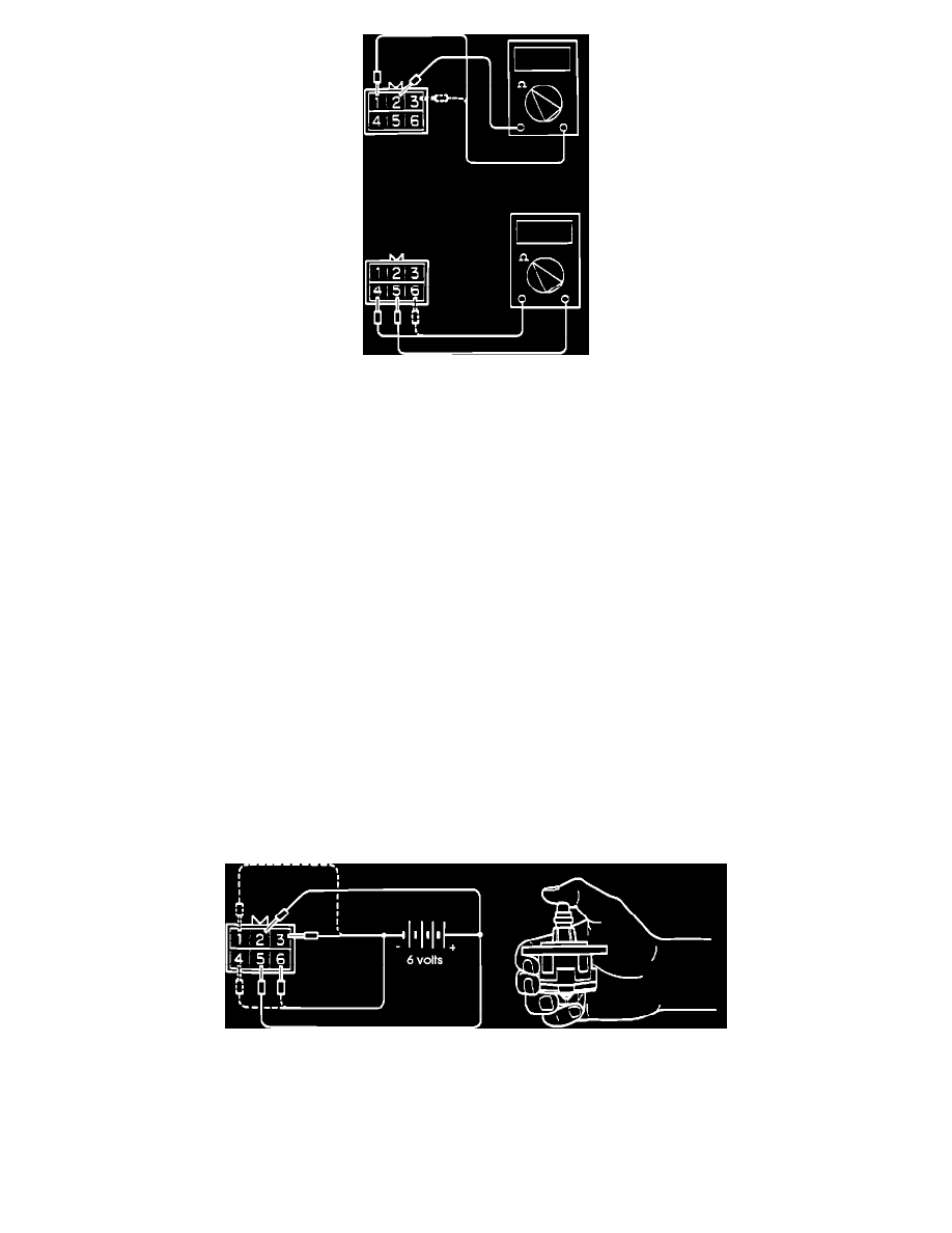
STEPPER MOTOR COIL RESISTANCE CHECK
1. Disconnect the electrical connector at the Idle Speed Control Servo.
2. Measure the servo's resistance, between terminal # 2 and terminal # 1 and then between terminal # 2 and terminal # 3, at the ISC Servo side of the
connector.
3. Measure the servo's resistance, between terminal # 5 and terminal # 6 and then between terminal # 5 and terminal # 4, at the ISC Servo side of the
connector.
Standard resistance:
-
Between terminal (2) and either terminal
(1) or (3) 28-33 Ohms [at 20°C (68°F)]
-
Between terminal (5) and either terminal
(6) or (4) 28-33 Ohms [at 20°C (68°F)]
STEPPER MOTOR OPERATION CHECK
Cautions:
a. The following test procedures must be followed in the exact sequence instructed. By applying power and/or a ground as instructed, circuits
within the servo are activated properly. Skipping a testing step will produce inaccurate results, which may lead to the unnecessary replacement
of a component.
b. Do NOT clamp the servo into a vise.
c. Assistance may be helpful in completing these test procedures.
1. Remove the Idle Speed Control Stepper Motor.
Refer the COMPONENT REPLACEMENT AND REPAIR for Throttle Body removal procedures.
Checking The Stepper Motor Operation
2. Connect the positive leads of a 6 volt power source to terminals # 2 and # 5 of the ISC Servo.
3. While holding the ISC Servo, connect the negative leads of the power source to each terminal IN SEQUENCE.
A slight vibration should result at each connection.
a. Connect the negative terminal of the power source to the ISC Servo connectors terminals # 3 and # 6.
b. Connect the negative terminal of the power source to the ISC Servo connectors terminals # 1 and # 6.
c. Connect the negative terminal of the power source to the ISC Servo connectors terminals # 1 and # 4.