
Laser FWD L4-1997cc 2.0L DOHC Turbo (1993)
d. Connect the negative terminal of the power source to the ISC Servo connectors terminals # 3 and # 4.
e. Connect the negative terminal of the power source to the ISC Servo connectors terminals # 3 and # 6.
4. Repeat the above test procedure in reverse. Starting with step e. and ending with step a..
If vibration is felt at each step procedure, the servo can be considered to be operating normally.
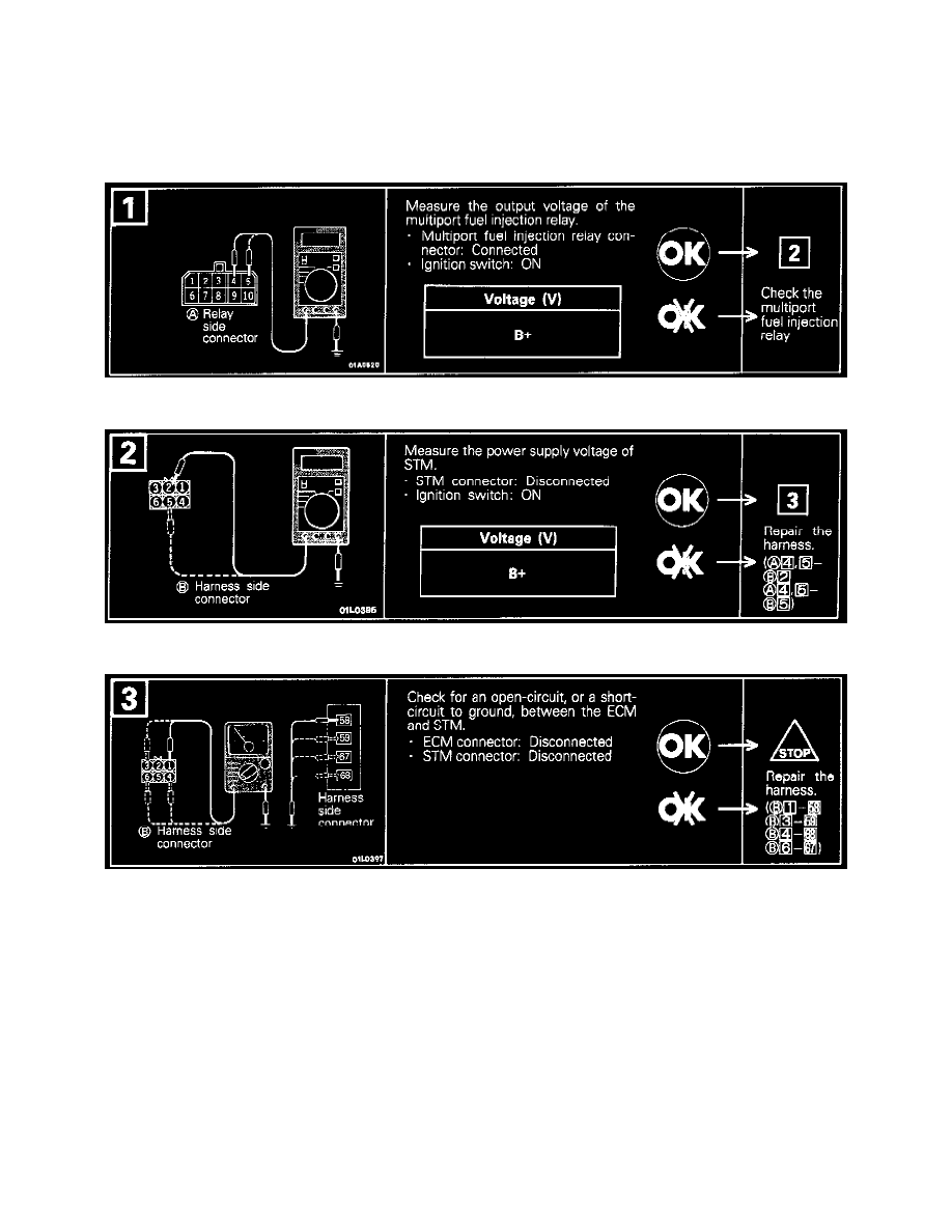
Harness Inspection
Step 1
Step 2
Step 3
TROUBLESHOOTING HINTS
1. If the number of steps increases to 120 or decreases to 0, a defect may exists in the stepper motor or the drive circuit.
2. If the number of steps is small, check whether air is sucked or not.
3. If the number of steps is large, deposits may stick to the throttle valve area increasing the resistance of the engine.
4. If the components of the engine are proper but the step is abnormal, adjust engine speed adjusting screw.