
Laser FWD L4-1997cc 2.0L DOHC Turbo (1993)
Main Relay (Computer/Fuel System): Description and Operation
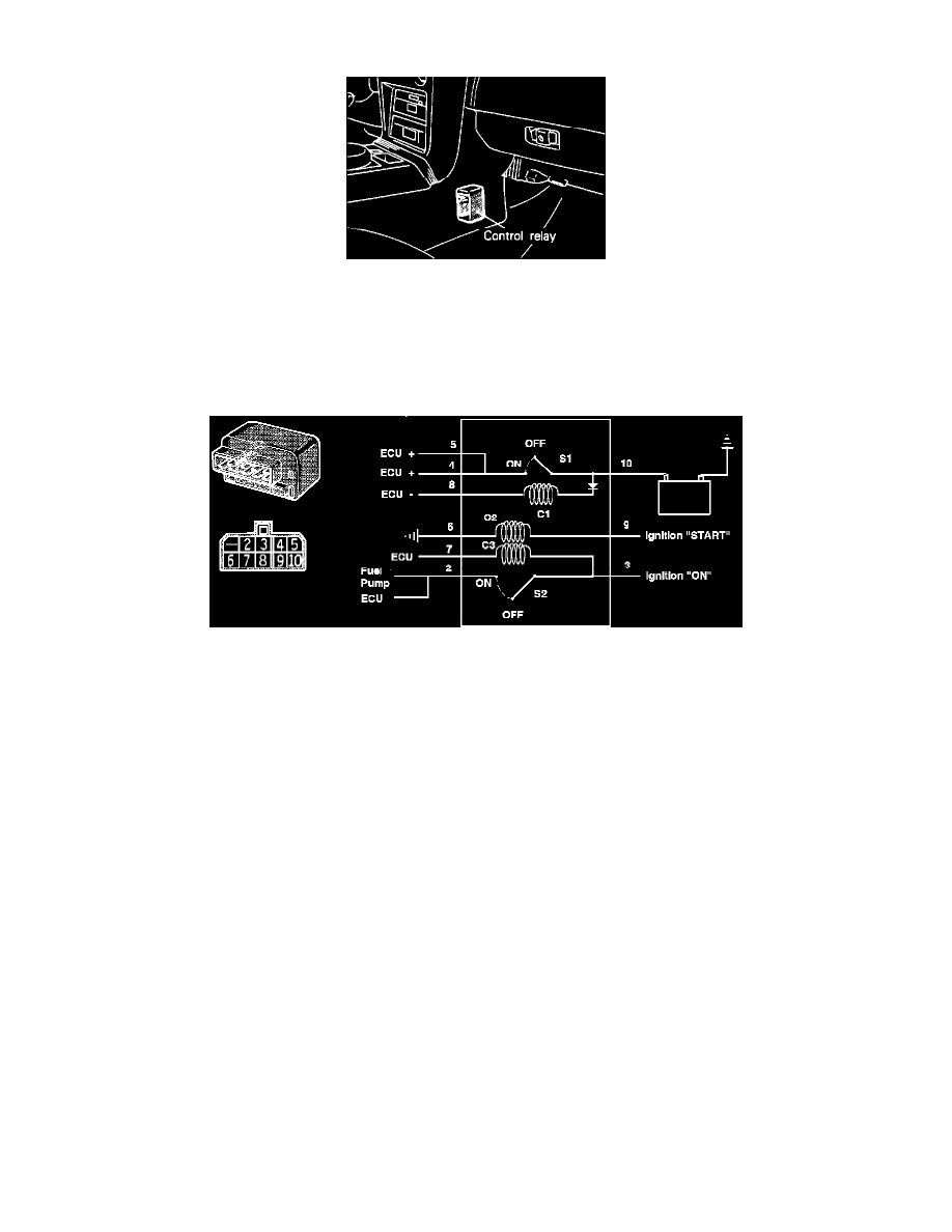
Control Relay Location
Purpose
The control relay supplies positive current to purge solenoid, air flow sensor, ECU, and injectors.
Location
The control relay is located in front of the center console.
Control Relay
Operation
When the key is in the START position, current flows from the ignition switch through the control relay coil C2 to ground. This turns on control
relay switch S2, supplying battery voltage to the fuel pump. Once the engine starts and the key is in the ON position, the ECU supplies the ground
circuit to the control relay coil C3, keeping control relay switch S2 closed, energizing the fuel pump.
When switch S2 is closed, battery voltage is also supplied to the ECU so the ECU detects the power supply to the fuel pump. Additionally,
whenever the ECU detects this power supply (switch S2 closed), it will supply the ground circuit to control relay coil C1. This closes control relay
switch S1, supplying power to ECU and various other components (injectors, relays and sensors).
In the event of engine stall or other abnormal conditions, the ECU will interrupt the ground supply to control relay C1, opening control relay
switch S2. This will turn the fuel pump OFF.
Note: Failure of the control relay may interrupt power supply to the fuel pump, injectors and/or the ECU, resulting in start failure.