
Laser FWD L4-1997cc 20L Turbo Main Relay Testing
Main Relay (Computer/Fuel System): Testing and Inspection
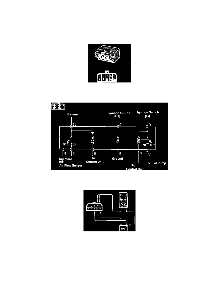
Relay Testing
Caution:
a. When applying battery voltage to the Control Relay, verify power source connections are to the correct terminals. Otherwise, the Control
Relay will be damaged.
b. The following test procedures should be performed in the order instructed. If not, inaccurate results and damage to the relay may occur.
Control Relay And Connector
1. Disconnect the Control Relay electrical connector, and remove the relay.
MPI Control Relay Circuitry
2. Connect a lead wire with alligator clips from the positive terminal of the battery to terminal # 10 of the relay.
Checking The Control Relay
3. Check for voltage from terminals # 4 and # 5 to ground, when the lead wire from the negative terminal of the battery is connected to terminal # 8
of the relay.
Battery voltage should exist during connection.
4. Connect the lead wire from the negative terminal of the battery to terminal # 6 of the Control Relay.