
Testing and Inspection: Engine Control Module Component Tests (Page 1722)
0 VDC when terminal 7 is NOT connected.
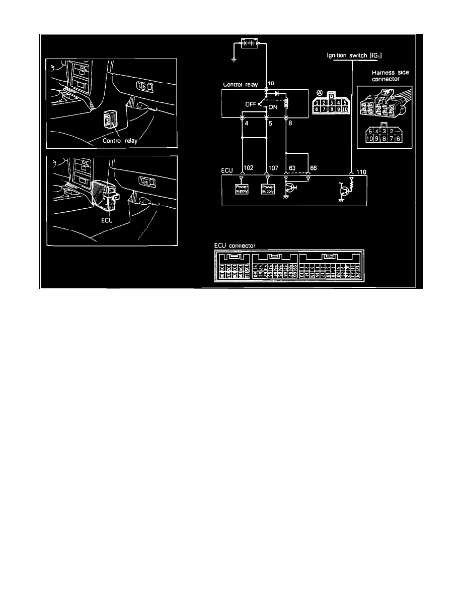
Power Supply Circuit
KEY "ON" POWER CIRCUIT
1. Disconnect the negative battery cable and the ECM connector.
2. Reconnect the negative battery cable and turn the key to the ON position.
3. Using a volt meter, check for voltage between ECM harness connector terminal 110 and ground.
Voltage
System voltage.
4. Turn the key to the OFF position and disconnect the control relay.
5. Using a volt meter, check for voltage between relay harness connector terminal 10 and ground.
Voltage
System voltage.
6. Disconnect the negative battery cable and the ECM connector.
7. Using an ohm meter check for continuity between relay harness connector 8 and ECM harness connectors 63 and 66.
Continuity
Should exist.
8. Using an ohm meter check for continuity between relay harness connector 4 and ECM harness connectors 102 and 107.
Continuity
Should exist.
9. Using an ohm meter check for continuity between relay harness connector 5 and ECM harness connectors 102 and 107.
Continuity
Should exist.
9. Using an ohm meter check for continuity between relay harness connector 4 and ground.