
Testing and Inspection: Component Tests and General Diagnostics | Page 1800
Testing The Power Transistor
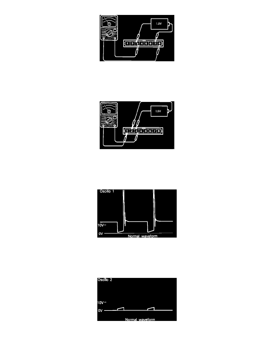
2. Connect the positive lead of an ohmmeter to terminal # 3, and the negative lead of the ohmmeter to terminal # 8.
Continuity should NOT exist.
3. Connect the positive lead of a 1.5 volt battery to terminal # 7 and the negative lead of the battery to terminal # 3.
Continuity should exist, while the battery is connected.
Testing The Power Transistor
4. Connect the positive lead of the ohmmeter to terminal # 3, and the negative lead of the ohmmeter to terminal # 1.
Continuity should NOT exist.
5. Connect the positive lead of a 1.5 volt battery to terminal # 2 and the negative lead of the battery to terminal # 3.
Continuity should exist, while the battery is connected.
Primary Ignition Coil Signal Pattern
OSCILLOSCOPE TEST
1. Run engine at idle speed.
2. Connect the scope probe to pick-up point #1 shown in the system schematic diagram and compare the primary ignition coil signal to the pattern
shown.
Power Transistor Control Signal Pattern
3. Run engine at idle speed.