
Laser FWD L4-1997cc 2.0L DOHC Turbo (1993)
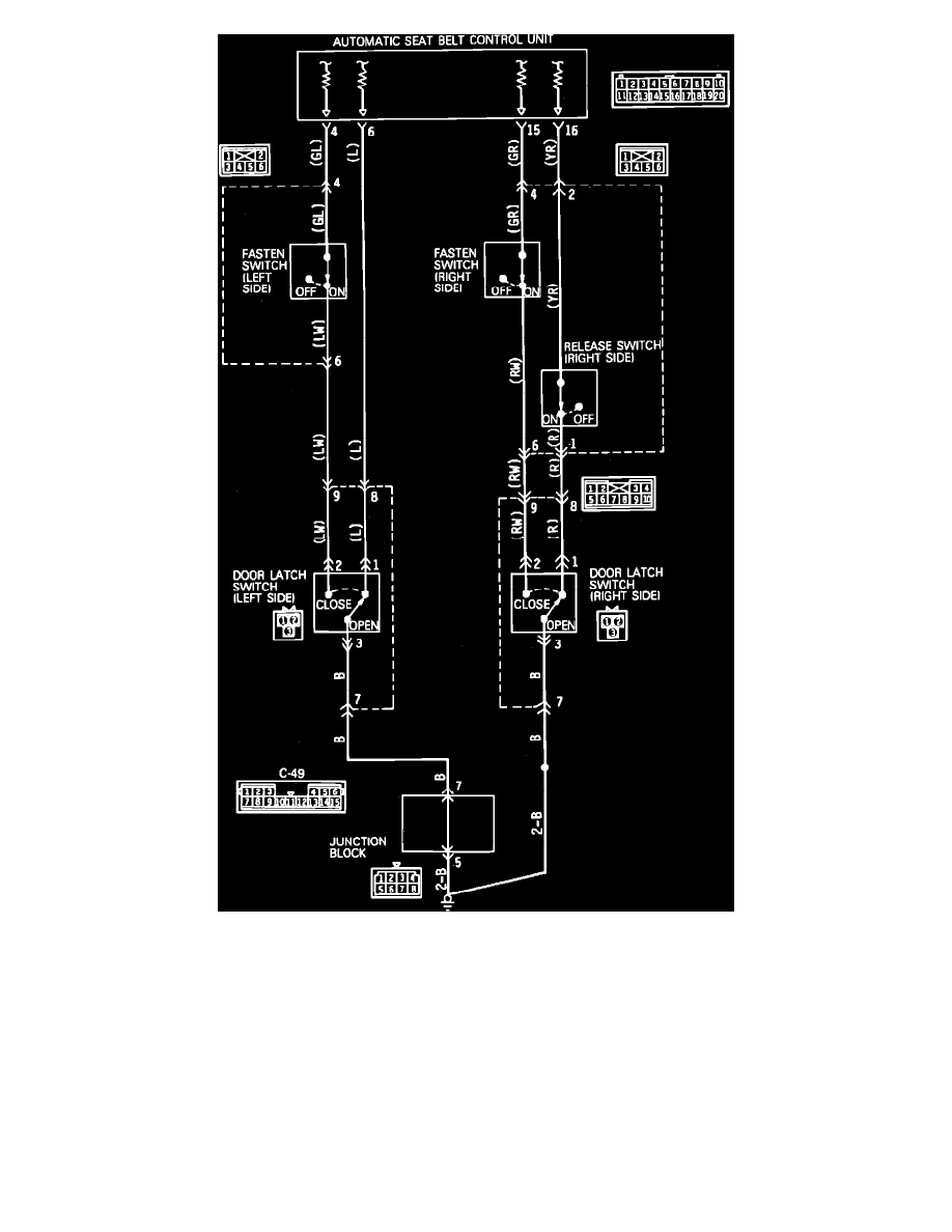
Fig. 146 Door Latch Switch, Fasten Switch & Release Switch (passenger's Side) Circuit Diagram
1.
Disconnect door latch switch harness connector.
2.
Connect a suitable ohmmeter between door latch switch terminals 1 and 3, then terminals 2 and 3.
3.
Observe ohmmeter while opening and closing door.
4.
Infinite ohms should be indicated between terminals 1 and 3 when door is open, continuity should be indicated between terminals 1 and 3 when
door is closed.
5.
Continuity should be indicated between terminals 2 and 3 when door is open, infinite ohms should be indicated between terminals 2 and 3 when
door is closed.
6.
If resistance indicated is as specified, circuit is satisfactory. Proceed to step 8.
7.
If resistance indicated is not as specified, replace door latch switch.
8.
Connect ohmmeter between door latch switch connector terminal 3 and ground.
9.
Ohmmeter should indicate continuity.
10.
If continuity is indicated, circuit is satisfactory. Proceed to step 12.
11.
If continuity is not indicated, repair harness as necessary.