
Laser FWD L4-1997cc 2.0L DOHC Turbo (1993)
Key Reminder Switch: Testing and Inspection
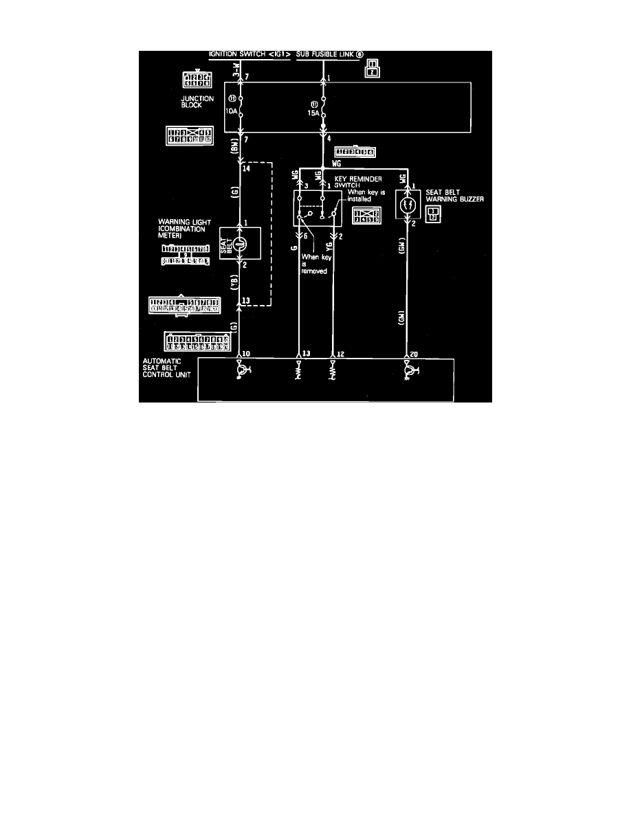
Fig. 144 Warning Light, Key Reminder Switch & Buzzer Circuit Diagram
1.
Check warning light circuit as follows:
a. Disconnect warning light harness connector.
b. Connect a suitable voltmeter between warning light connector terminal 1 and ground.
c. Turn ignition switch On.
d. Voltage indicated should be approximately 12 volts.
e. If voltage indicated is as specified, circuit is satisfactory. Proceed to step g.
f.
If voltage indicated is not as specified, repair circuit as necessary.
g. Connect warning light harness connector.
h. Disconnect control unit harness connector.
i.
Connect a suitable voltmeter between control unit connector terminal 1 and ground.
j.
Turn ignition switch On.
k. Voltage indicated should be approximately 12 volts.
l.
If voltage indicated is as specified, circuit is satisfactory. Proceed to step 2.
m. If voltage indicated is not as specified, repair circuit or replace warning light bulb as necessary.
2.
Check key reminder switch circuit as follows:
a. Disconnect key reminder switch harness connector.
b. Connect a suitable voltmeter between key reminder switch connector terminal 1 and ground, then terminal 3 and ground.
c. Voltage indicated should be approximately 12 volts.
d. If voltage indicated is as specified, circuit is satisfactory. Proceed to step f.
e. If voltage indicated is not as specified, repair circuit as necessary.
f.
Connect key reminder switch harness connector.
g. Disconnect control unit harness connector.
h. Remove key from ignition switch.
i.
Connect a suitable voltmeter between control unit connector terminal 13 and ground.
j.
Voltage indicated should be approximately 12 volts.
k. If voltage indicated is as specified, circuit is satisfactory. Proceed to step m.
l.
If voltage indicated is not as specified, repair circuit as necessary.
m. Connect a suitable voltmeter between control unit connector terminal 12 and ground.
n. Voltage indicated should be 0 volts.
o. If voltage indicated is as specified, circuit is satisfactory. Proceed to step q.