Laser FWD L4-1997cc 2.0L DOHC Turbo (1993)

Door Switch: Testing and Inspection
Passenger's Side
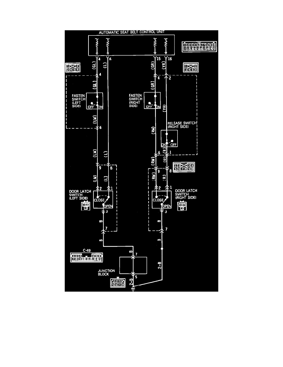
Fig. 146 Door Latch Switch, Fasten Switch & Release Switch (passenger's Side) Circuit Diagram
1.
Disconnect door latch switch harness connector.
2.
Connect a suitable ohmmeter between door latch switch terminals 1 and 3, then terminals 2 and 3.
3.
Observe ohmmeter while opening and closing door.
4.
Infinite ohms should be indicated between terminals 1 and 3 when door is open, continuity should be indicated between terminals 1 and 3 when
door is closed.
5.
Continuity should be indicated between terminals 2 and 3 when door is open, infinite ohms should be indicated between terminals 2 and 3 when
door is closed.
6.
If resistance indicated is as specified, circuit is satisfactory. Proceed to step 8.
7.
If resistance indicated is not as specified, replace door latch switch.
