
Laser FWD L4-1997cc 2.0L DOHC Turbo (1993)
Camshaft Position Sensor: Component Tests and General Diagnostics
Component Testing
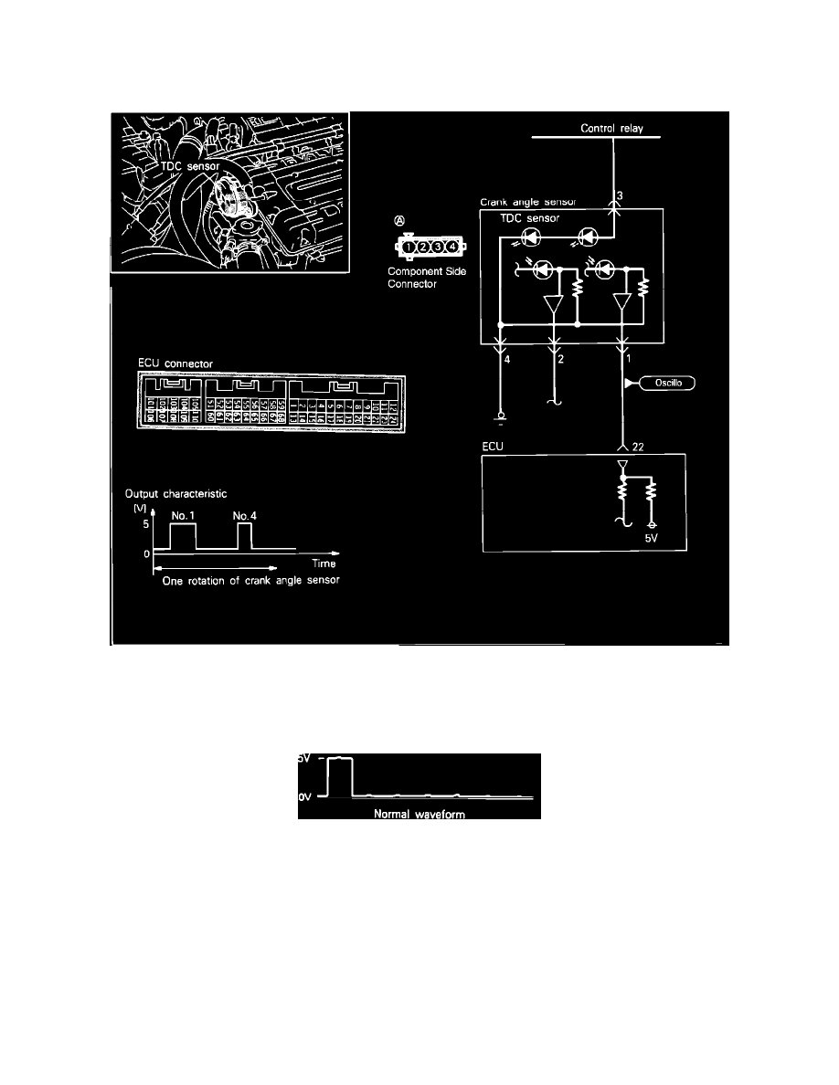
Top Dead Center (TDC) Sensor Circuit
OSCILLOSCOPE TESTING PROCEDURE:
1. Connect test leads from the oscilloscope to the #1 terminal of the sensor connector and run the engine at idle speed.
Scope Test Waveform--single Rotation Of The Distributor
2. Check the waveform and compare it to the diagram shown.
VOLTAGE TESTING PROCEDURE:
1. Connect a voltmeter between terminal 3 and 1 of the crank angle sensor connector.
Terminal 1: Camshaft (TDC) signal
Terminal 4: Sensor ground
2. Measure the output voltage of the terminals while cranking the engine.
Standard approximate value
2.0 - 2.5v
3. When the voltage is abnormal, check the sensor power and ground circuits.