
Neon L4-2.0L DOHC (1996)
Radiator Cooling Fan Motor: Description and Operation
Circuit Operation
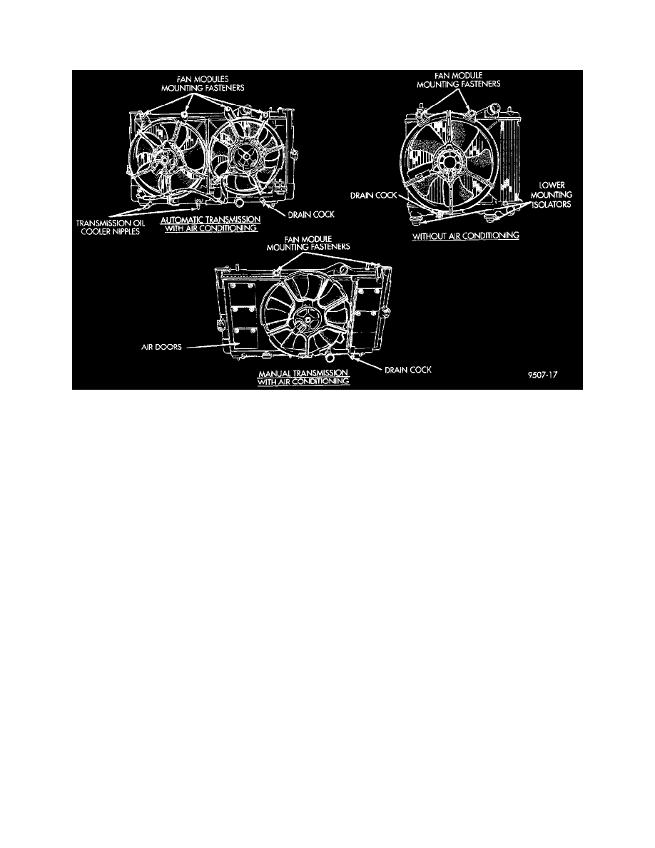
Cooling Fan Modules
Circuit Operation
The radiator fan system used in this vehicle uses one relay located in the Power Distribution Center (PDC).
Power for the coil side of the relay is supplied on circuit F12. This circuit is HOT in the START and RUN position and protected by a 15 Amp fuse
located in cavity 10 of the fuse block.
Power for the fuse is supplied on circuit A21 from the ignition switch. Power for the A21 circuit is supplied by circuit A1 from the PDC. The A1
circuit is protected by a 30 Amp fuse in the PDC.
Power for the contact side of the relay is supplied on circuit A16. This circuit is HOT at all times and protected by a 30 Amp fuse located in the PDC.
Ground for the coil side of the relay is controlled by the Powertrain Control Module (PCM). When the PCM determines the need for fan operation the
PCM supplies the ground path for circuit C27. This circuit connects to cavity 55 of the PCM connector. This causes the contacts in the relay to
CLOSE connecting circuits A16 and C25. The C25 circuit connects to the radiator fan motor. Ground for the motor is supplied on circuit Z1.