
Neon L4-2.0L DOHC (1996)
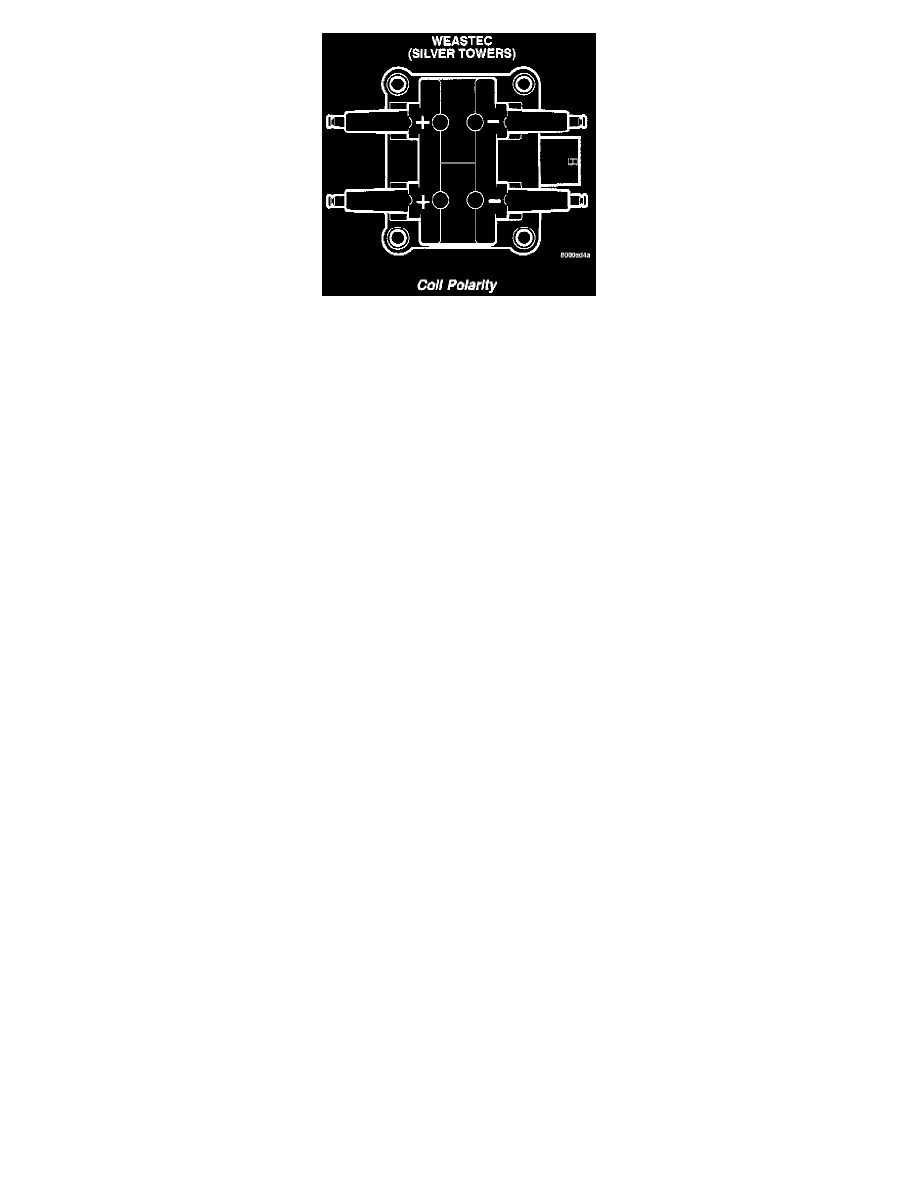
Coil Polarity
CIRCUIT OPERATION
Circuit A14 is a bus bar in the Power Distribution Center (PDC), and connects to battery voltage. The contact side of the Automatic Shut Down (
ASD) relay connects circuit A14 and circuit A142. A 20 Amp fuse in the PDC protects circuits A14 and A142.
Circuit A14 also supplies voltage to the coil side of the ASD relay The Powertrain Control Module (PCM) controls the ground path circuit for the
coil side of the ASD relay on circuit K51. Circuit K51 connects to cavity 67 of the PCM connector.
Circuit A142 supplies voltage for the ignition coil pack. The coil pack consists of two individual coils molded together. The PCM controls the
ground circuit of each coil.
-
Circuit K19 is the ground circuit for the ignition coil that fires spark plugs # 1 and # 4. Circuit K19 connects to cavity 2 of the PCM.
-
Circuit K17 is the ground circuit for the ignition coil that fires spark plugs #2 and # 3. Circuit K17 connects to cavity 3 of the PCM.