
Neon L4-2.0L SOHC (1995)
Tachometer: Service and Repair
Fig. 3 Cluster Assembly
CAUTION: Cluster MUST be stored in a face up position or damage will occur to the gauge operation.
NOTE: Before disassembling the cluster check for a defective sending unit or wiring.
CLUSTER PRINTED CIRCUIT BOARD REMOVAL
1. Remove cluster, refer to Cluster Removal.
2. Remove six attaching screws and rear cover. The bottom screws attaching lens to housing can be accessed without removing foam pad.
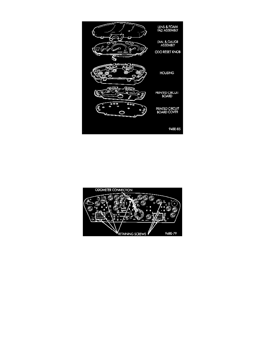
Fig. 4 Printed Circuit Boards
3. Disconnect odometer connector and remove seven attaching printed circuit (PC) board and housing.
4. Carefully remove printed circuit board from the cluster.
5. For installation reverse above procedures. Carefully place board on the cluster and ensure that the odometer connector is placed through the board.
Gently press board on cluster with a slight rocking motion to assure pins on gauges line up.
GAUGE REMOVAL
1. Remove cluster, refer to Cluster Removal.
2. Remove six screws attaching PC board cover. The bottom screws attaching lens to housing can be accessed without removing foam pad.
3. Disconnect odometer connector.
4. Remove six lens screws and remove lens.
5. Carefully pry out dial and gauge assembly.
6. For installation reverse above procedures.