
Neon L4-2.0L SOHC (1995)
Idle Speed/Throttle Actuator - Electronic: Service and Repair
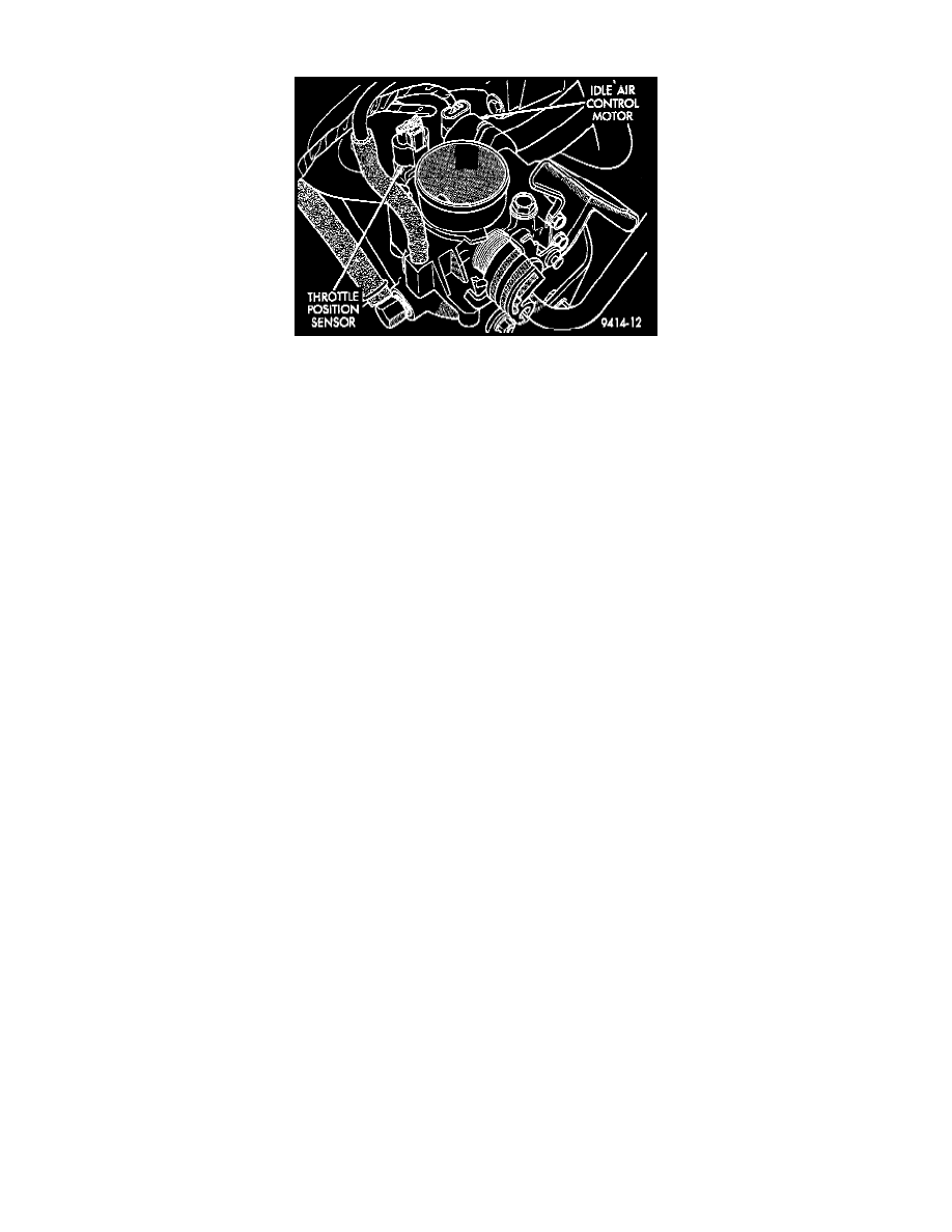
Fig. 14 Throttle Position Sensor And Idle Air Control Motor
NOTE: The idle air control motor attaches to the side of the throttle body (Fig. 14).
REMOVAL
1. Disconnect EVAP purge hose from throttle body.
2. Disconnect electrical connector from idle air control motor and throttle position sensor.
3. Remove throttle body. Refer to procedure.
4. Remove idle air control motor mounting screws.
5. Remove idle air control motor. Ensure 0-ring is removed with the motor.
INSTALLATION
1. The new idle air control motor has a new 0-ring installed on it. If pintle measures more than 1 inch (25 mm) it must be retracted. Use the DRB or
equivalent AIS Motor Open/Close Test to retract the pintle (battery must be connected.)
2. Carefully place idle air control motor into throttle body.
3. Install mounting screws. Tighten screws to 3 Nm (25 in lb) torque.
4. Install throttle body. Refer to procedure.
5. Attach electrical connectors to idle air control motor and throttle position sensor.
6. Install EVAP purge hose to throttle body nipple.