
Neon L4-2.0L SOHC (1995)
Wire Repair
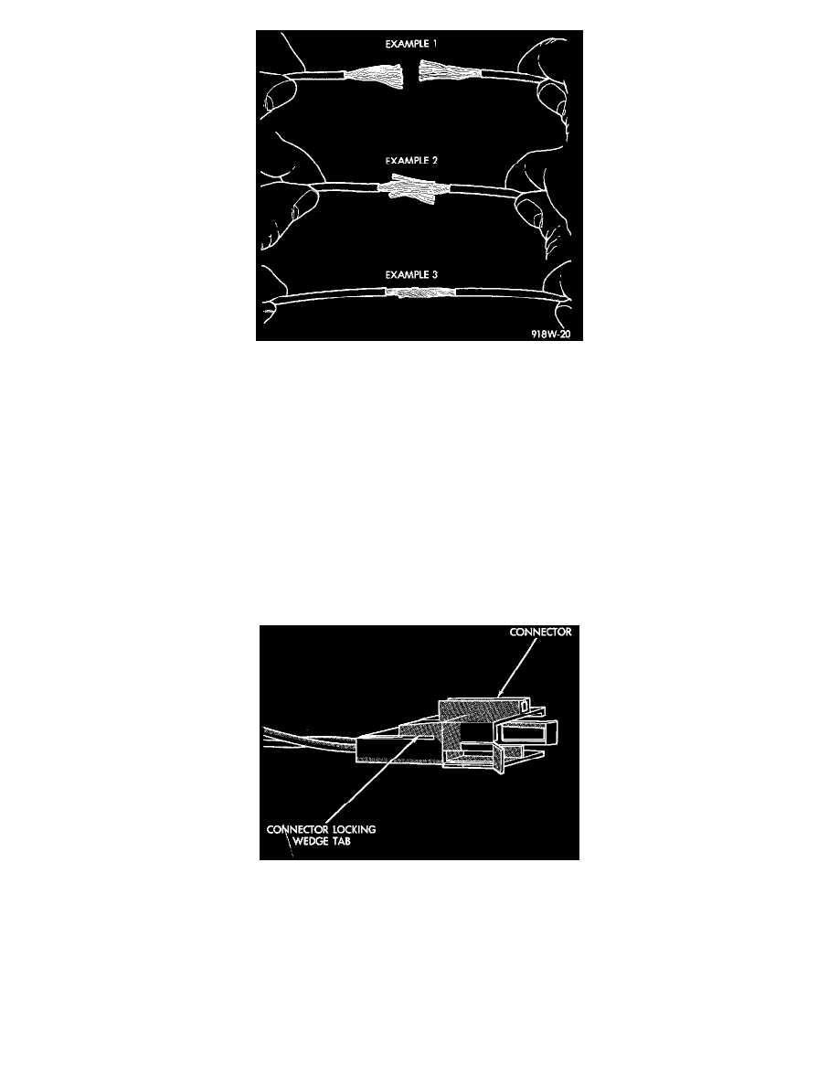
9. Spread the strands of the wire apart on each part of the exposed wires (Example 1).
10. Push the two ends of wire together until the strands of wire are close to the insulation (Example 2).
11. Twist the wires together (Example 3).
12. Solder the connection together using rosin core solder only. Do not use acid core solder.
13. Center the heat-shrink tubing over the joint and heat using a heat gun. Heat the joint until the tubing is tightly sealed and sealant comes out of both
ends of the tubing.
14. Repeat steps 8 through 13 for each wire.
15. Re-tape the wire harness starting 1-1/2 inches behind the connector and 2 inches past the repair.
16. Re-connect the repaired connector.
17. Connect the battery and test all affected systems.
Connector Replacement
1. Disconnect the battery.
2. Disconnect the connector (that is to be repaired) from its mating half/component.
Connector Locking Wedge
3. Remove the connector locking wedge, if required.