
Neon L4-2.0L SOHC (1995)
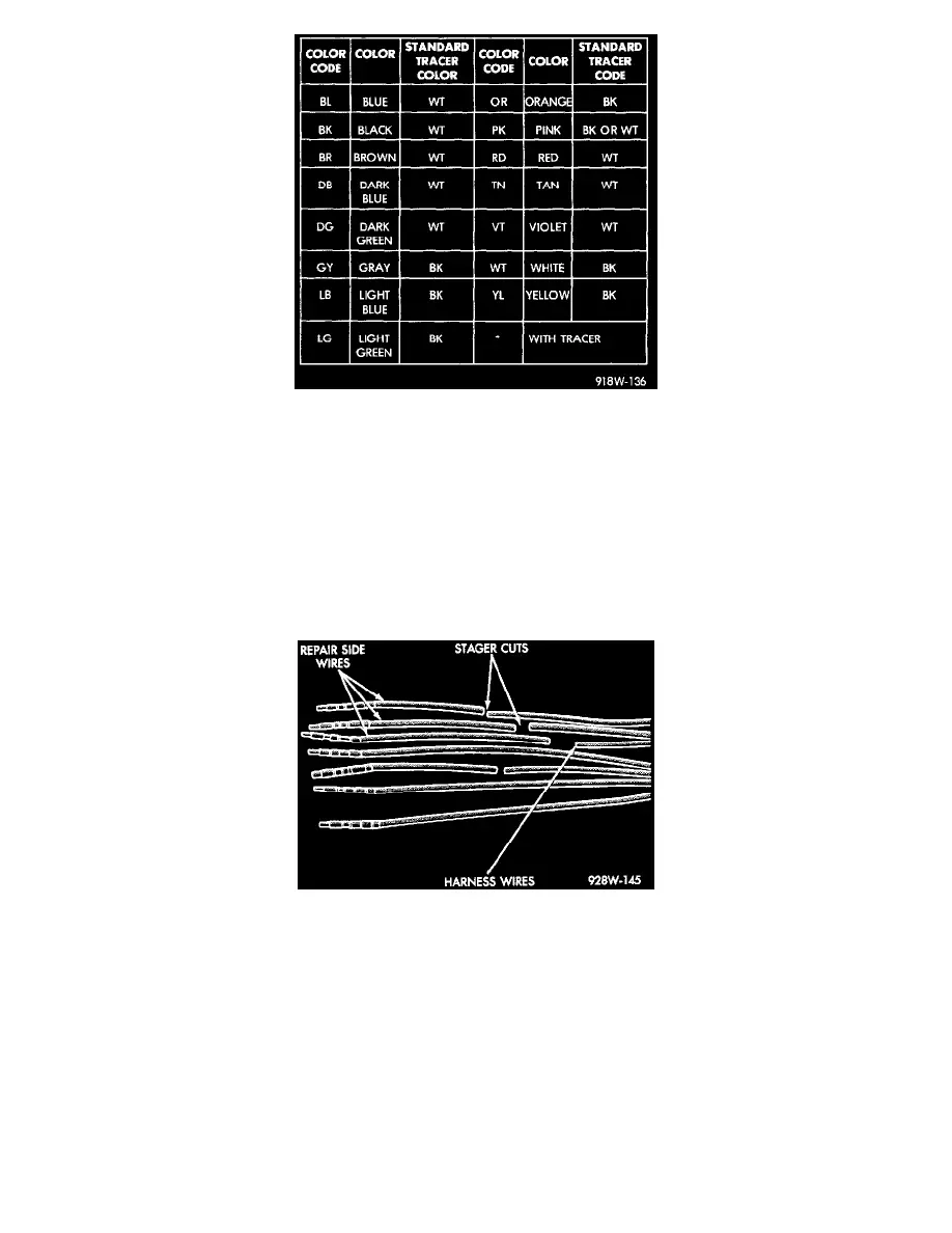
Fig.2 Wire Color Codes
Each wire shown in the diagrams contains a code which identifies the main circuit, part of the main circuit, gauge of wire, and color. The color is shown
as a two-letter code, which can be identified by referring to the Wire Color Code chart. If the wire has a tracer, and it is a standard color, an asterisk will
follow the main wire color. If the tracer is non-standard, the main wire color will have a slash (/) after it, followed by the tracer color.
Connector and Terminal Replacement
1. Disconnect battery.
2. Disconnect the connector (that is to be repaired) from its mating half/component.
3. Cut off the existing wire connector directly behind the insulator. Remove six inches of tape from the harness.
4. Stagger cut all wires on the harness side at 1/2 inch intervals.
5. Remove 1 inch of insulation from each wire on the harness side.
Stagger Cutting Wires (Typical)
6. Stagger cut the matching wires on the repair connector assembly in the opposite order as was done on the harness side of the repair. Allow extra
length for soldered connections. Check that the overall length is the same as the original.
7. Remove 1 inch of insulation from each wire.
8. Place a piece of heat-shrink tubing over one side of the wire. Be sure the tubing will be long enough to cover and seal the entire repair area.