
Neon L4-2.0L SOHC (1995)
Supplemental Restraint System (SRS) Control Module: Description and Operation
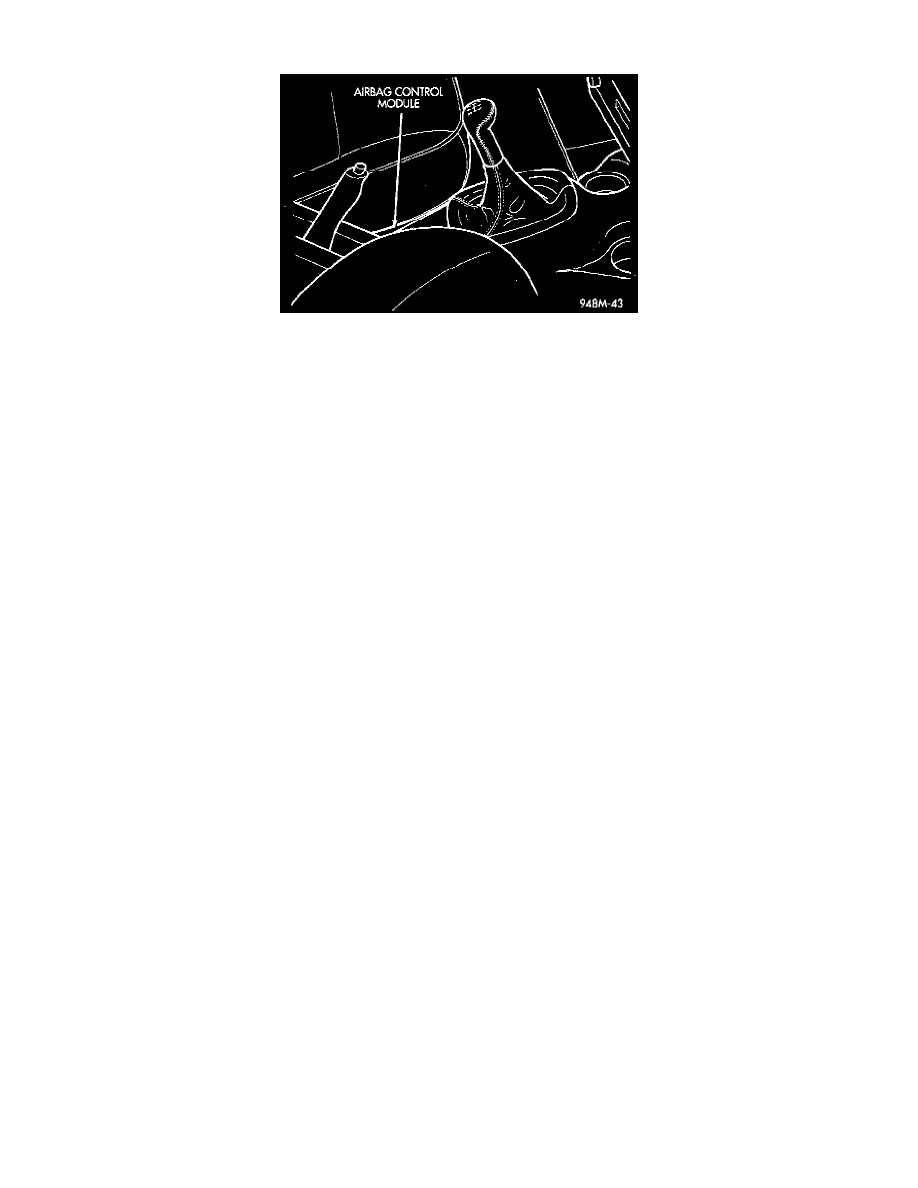
Fig. 3 Passenger Airbag
OPERATION
The Airbag Control Module (ACM) contains the safing sensor and energy reserve capacitor. The safing sensor is located inside the ACM. The
module is mounted on the tunnel/floor pan between the gear shift lever and the park brake lever. The safing sensor provides confirmation of a
crash, but does not discriminate severity. The ACM monitors the system to determine the system readiness. The ACM will store sufficient energy
to deploy the airbags for at least one second after the battery is disconnected. The ACM contains on-board diagnostics, and will illuminate the
AIRBAG warning lamp in the cluster when a fault occurs. The warning equipment is tested for six to eight seconds every time the vehicle is
started.
CIRCUIT OPERATION
Two different circuits supply battery voltage from the fuse block to the Airbag Control Module (ACM), F15 and F25. The F15 and F25 circuits
are connected to separate bus bars internal to the fuse block. Different circuits from the Power Distribution Center (PDC) and the ignition switch
supply battery voltage to the fuse block bus bars.
The F25 circuit supplies battery voltage - to the ACM only when the ignition switch is in the RUN position. The F15 circuit powers the ACM
when the ignition switch is in either the START or RUN position.
An internal bus bar in the ignition switch connects the A1 circuit from the PDC to the A21 circuit when the switch is in either the START or RUN
position. The A21 circuit supplies battery voltage to the fuse block bus bar that feeds the F15 circuit. A 30 amp maxi fuse in the PDC protects the
Al and A21 circuits. A 10 amp fuse in the fuse block, cavity 9, protects the F15 circuit.
When the ignition switch is in the RUN position, it connects the A2 circuit from the PDC to the A22 circuit. The A22 circuit supplies battery
voltage to the fuse block bus bar that feeds the F25 circuit. A 30 amp maxi fuse in the PDC protects the A2 and A22 circuits. A 10 amp fuse in the
fuse block, cavity 5, protects the F25 circuit.
The ACM has a case ground and an external dedicated ground, circuit Z6. The dedicated ground connects to the instrument panel right center
support.