
Neon L4-2.0L VIN C (1997)
Electronic Brake Control Module: Description and Operation
Controller Antilock Brake
PURPOSE
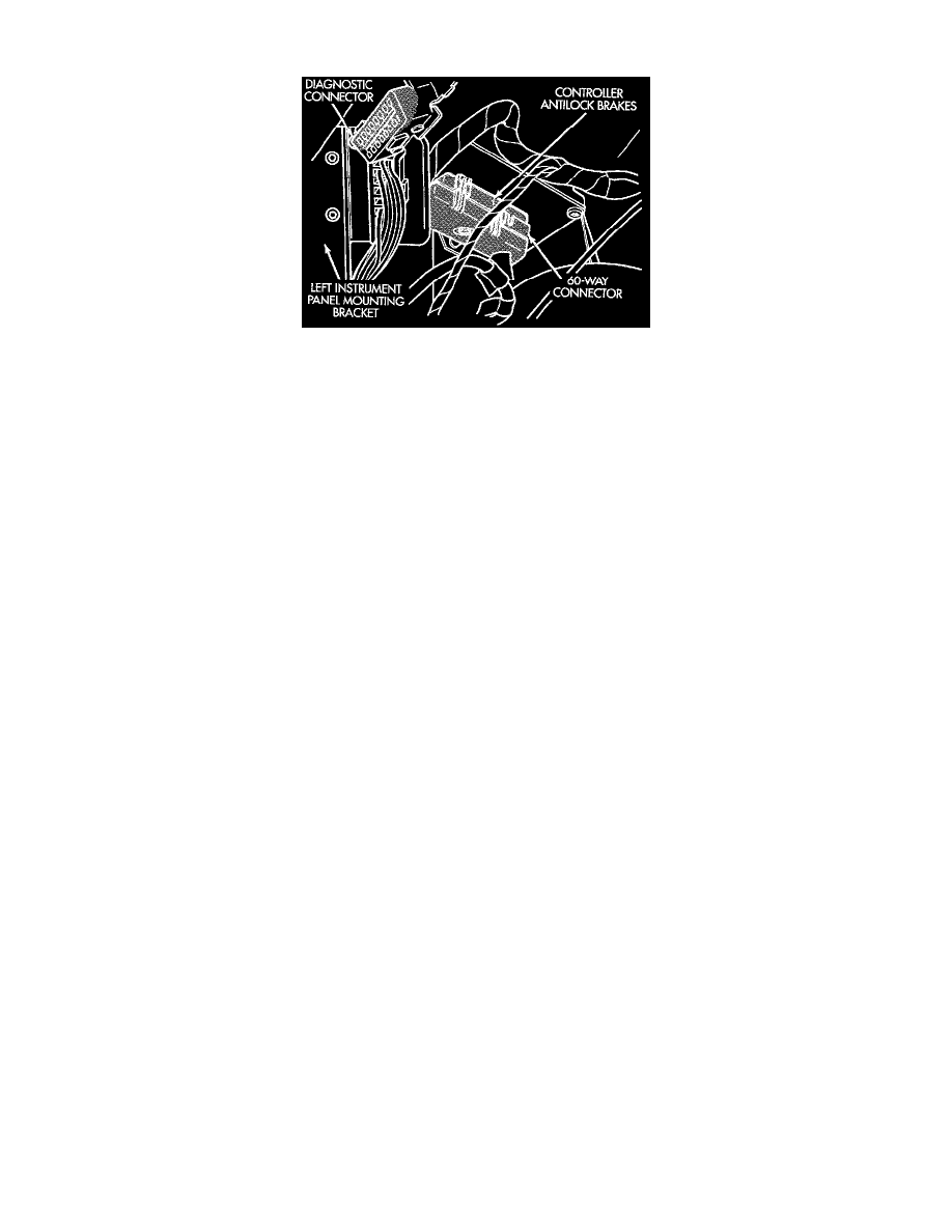
The Controller Antilock Brake (CAB) is a microprocessor based device which monitors the Antilock Brake System (ABS) during normal braking
and controls it when in an ABS stop. The CAB is mounted under the instrument panel on the drivers side kick panel. The CAB uses a 60 way
electrical connector on the vehicle wiring harness. The power source for the CAB is through the ignition switch in the Run or On position.
NOTE: The CAB is not on the Chrysler Collision Detection (CCD) bus.
THE PRIMARY FUNCTIONS OF THE CAB
-
Detect wheel locking tendencies.
-
Control fluid modulation to the brakes while in ABS mode.
-
Monitor the system for proper operation.
-
Provide communication to the DRB scan tool while in diagnostic mode.
The CAB Continuously Monitors - the speed of each wheel through the signals generated at the Wheel Speed Sensors to determine if any wheel
is beginning to lock. When a wheel locking tendency is detected, the CAB commands the Hydraulic Control Unit (HCU) to modulate brake fluid
pressure in some or all of the hydraulic circuits. The CAB continues to control pressure in individual hydraulic circuits until a locking tendency is
no longer present.
The ABS System Is Constantly Monitored - by the CAB for proper operation. If the CAB detects a fault, it will turn on the Amber ABS
Warning Lamp and disable the ABS braking system. The normal Non ABS braking system will remain operational.
The CAB Contains A Self-diagnostic Program - which will turn on the Amber ABS Warning Lamp when a ABS system fault is detected.
Faults Are Then Stored - in a diagnostic program memory. There are multiple fault messages which may be stored in the CAB and displayed
through the DRB. These fault messages will remain in the CAB memory even after the ignition has been turned off. The fault messages can be
cleared by using the DRB diagnostics tester, or they will be automatically cleared from the memory after the vehicle is driven approximately
3500 miles.
CONTROLLER ANTILOCK BRAKE INPUTS
^ Four wheel speed sensors.
^ Stop lamp switch.
^ Ignition switch.
^ System relay voltage.
^ Ground.
^ Pump/Motor Relay Monitor
^ Diagnostics Communications
CONTROLLER ANTILOCK BRAKE OUTPUTS
^ 4 Decay Solenoids
^ ABS warning lamp.
^ System relay actuation.
^ Diagnostic communication.
^ Pump motor relay actuation