
Neon L4-2.0L VIN C (1997)
Hydraulic Control Unit: Description and Operation
General Information
Hydraulic Control Unit
GENERAL INFORMATION
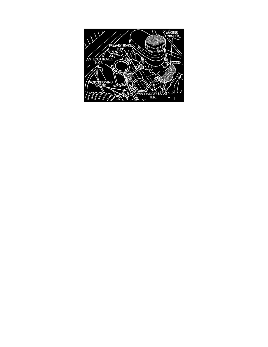
The Hydraulic Control Unit (HCU) is located under the master cylinder and power brake booster and is mounted to the left frame rail. The HCU
contains the following components for controlling the vehicle's braking system during Antilock Brake System (ABS) braking: 4 Decay Valves, 4
Shuttle Valves, 2 Fluid Sumps, a Pump/Motor and a relay box. Also attached to the HCU are the rear brake Proportioning Valves and the vehicles
6 hydraulic brake tubes.
Decay Solenoids
There are 4 decay solenoids, one for each wheel. In the released position they provide a fluid path from the master cylinder to the wheel brakes of
the vehicle. In the actuated (decay) position, they provide a fluid path from wheel brakes of the vehicle to the sumps. The Decay solenoids are
spring loaded in the released (build) position during normal braking.
Shuttle Valves
There are 4 Shuttle Valves, one for each wheel. The Shuttle Valve is a hydraulically actuated valve which shuttles when the decay solenoid and
pump are energized. This places an orifice (restriction) in the line between the pump and the decay solenoid. This restriction provides a controlled
build rate to each wheel brake during an ABS stop. The Shuttle Valve will remain in the orificed position until the ABS cycle is complete. When
the ABS cycle has been completed the decay solenoids will return to their released position which will equalize the pressure across the Shuttle
Valves. When the pressure equalizes, the spring loaded Shuttle Orifice valves will return to the unrestricted position.
Fluid Sumps
There are two fluid sumps in the HCU, one each for the primary and secondary hydraulic circuits. The fluid sumps temporarily store brake fluid
that is decayed from the wheel brakes during an ABS cycle. This fluid is then delivered to the pump to provide build pressure. The typical pressure
in the sumps is 50 psi, during ABS operation only.
Pump Motor Assembly
The HCU contains 2 Pump Assemblies, one each for the primary and secondary hydraulic circuits. Both pumps are driven by a common electric
motor which is part of the HCU. The pumps pick up fluid from the sumps to supply build pressure to the brakes during an ABS stop. The motor
only runs during an ABS stop and is controlled by the Controller Antilock Brake (CAB) via the Pump/Motor Relay. The Pump/Motor Assembly is
not a serviceable item. If it requires service the HCU must be replaced.
Relay Box
ABX-4 utilizes two relays contained in a relay box mounted to the HCU. The relay box contains a System Relay and a Pump/Motor Relay. A
single 10-way connector provides the electrical interface. The relay box is serviceable as an assembly.