
Neon L4-2.0L VIN C (1997)
Radiator Cooling Fan Motor: Description and Operation
Circuit Operation
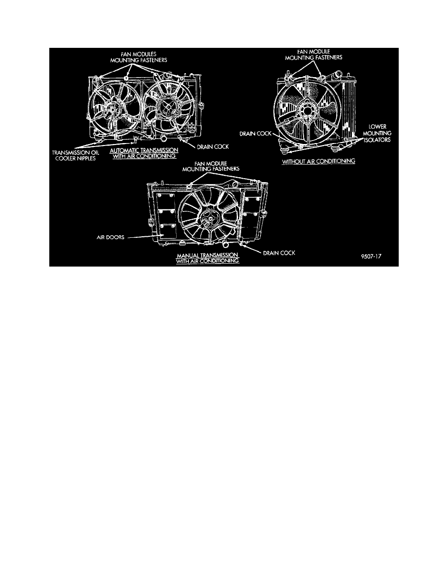
Cooling Fan Modules
Circuit Operation
The radiator fan system used in this vehicle uses a solid state relay that controls the speed of the radiator fan.
Power for the relay is supplied on circuit A16 This circuit is HOT at all times and protected by a 30 Amp fuse located in the Power Distribution
Center (PDC).
Ground for the coil side of the relay is controlled by the Powertrain Control Module (PCM). When the PCM determines the need for fan operation the
PCM supplies the ground path for circuit K173. This circuit connects to cavity 18 of the PCM connector.
From the relay, circuit C25 connects to the radiator fan motor(s). On vehicles equipped with the manual transmission only one radiator fan is used. For
vehicles equipped with an automatic transmission there are two radiator fans used.
Ground for the radiator fans is supplied on circuit Z1.