
Neon L4-2.0L VIN C (1997)
Data Link Connector: Description and Operation
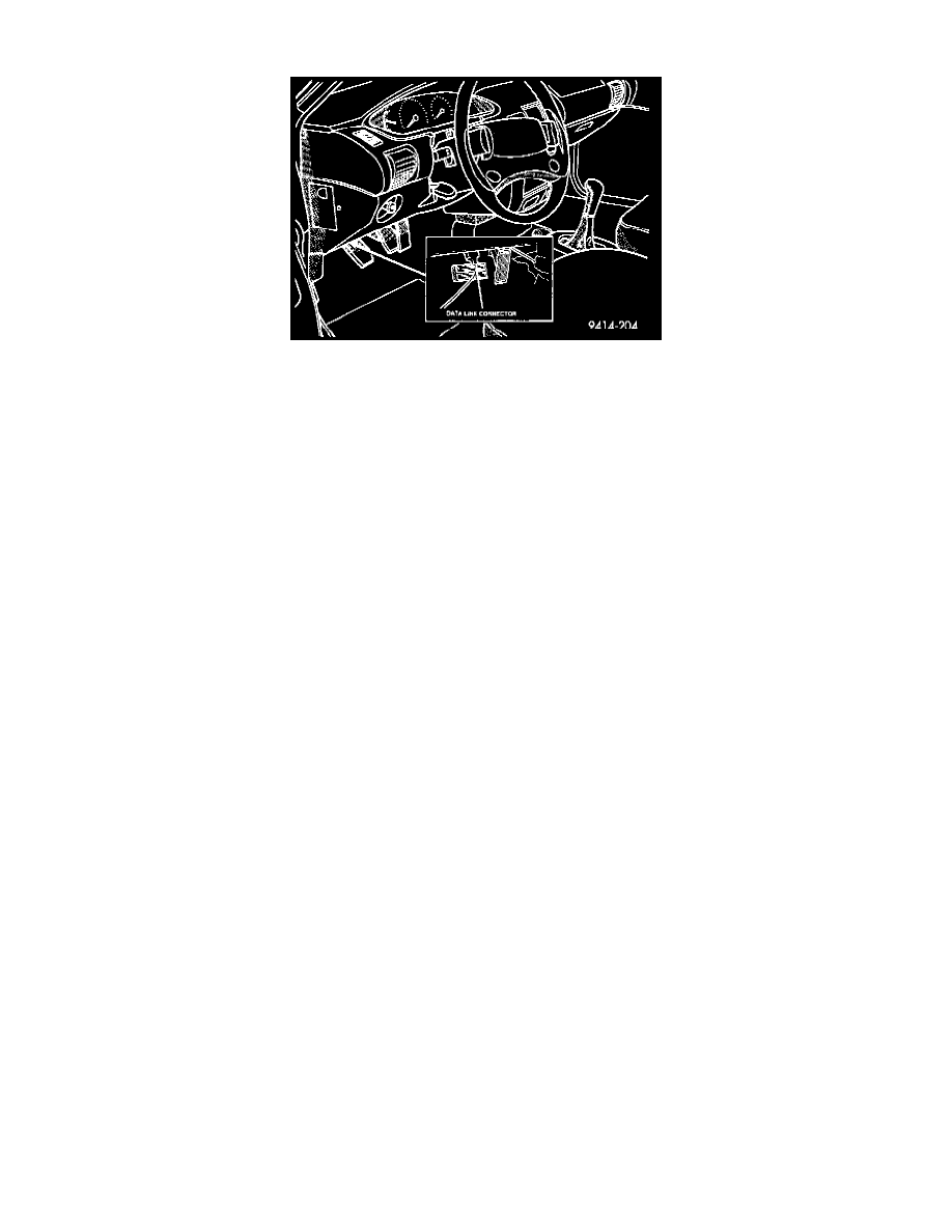
Fig. 3 Data Link Connector
PURPOSE
Communication link to Powertrain Control Module (PCM)
Technician can access inputs and memory including:
-
Sensor input values
-
Diagnostic Trouble Codes (DTC's) stored in memory
-
Last deactivation cause (i.e.. speed control last shut off by; speed control switch, brake switch or no crank sensor signal).
Technician can actuate most PCM output devices.
NOTE: Monitoring inputs, reading memory -- other than codes -- and actuating output devices can only be accomplished through the use of a scan tool.
SEE Computers and Control System/Testing and Inspection.
CIRCUIT OPERATION
Circuit A14 supplies battery voltage to the universal data link connector. Circuit A14 originates in the Power Distribution Center (PDC) and
connects to a battery fed bus bar. A 20 Amp fuse protects circuit A14.
A twisted pair of wires, circuits D1 and D2, from the Airbag Control Module (ACM) connect to the universal data link connector.
Ground circuit Z12 splices to two cavities of the data link connector. The Z12 circuit also connects to cavities 10 and 50 of the PCM connector.
Circuit D20 connects to cavity 75 of the PCM and to the universal data link connector. Circuit D20 is the SCI receive circuit for the PCM.
Circuit D21 connects to cavity 65 of the PCM and to the universal data link connector. Circuit D21 is the SCI transmit circuit for the PCM. The
D21 circuit splices to the ABS module.