
Neon L4-2.0L VIN C (1997)
Knock Sensor: Description and Operation
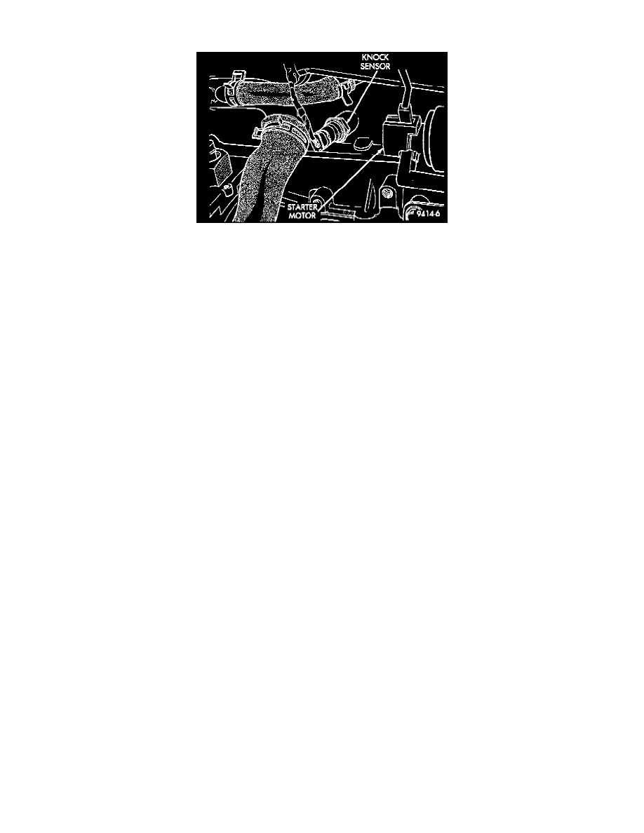
Fig. 11 Knock Sensor
PURPOSE
When the knock sensor detects a knock in one of the cylinders, it sends an input signal to the PCM. In response, the PCM retards ignition timing
for all cylinders by a scheduled amount.
OPERATION
Knock sensors contain a piezoelectric material which sends an input voltage (signal) to the PCM. As the intensity of the engine knock vibration
increases, the knock sensor output voltage also increases.
The knock sensor threads into the side of the cylinder block in front of the starter (Fig. 11).
CAUTION: Over or under tightening effects knock sensor performance, possibly causing improper spark control.
CIRCUIT OPERATION
The knock sensor provides an input to the Powertrain Control Module (PCM) on circuit K42. Circuit K42 connects to cavity 24 of the PCM
connector.
The PCM provides ground for the knock sensor signal (circuit K42) through circuit K4. Circuit K4 connects to cavity 43 of the PCM connector.