
Neon L4-2.0L VIN C (1997)
Manifold Pressure/Vacuum Sensor: Description and Operation
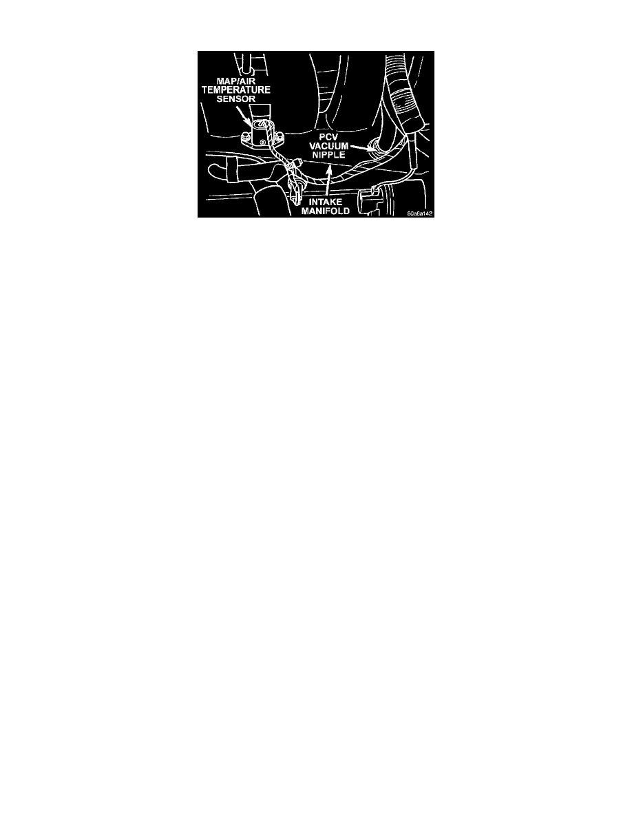
MAP/IAT Sensor
OPERATION
The PCM supplies 5 volts to the MAP sensor The MAP sensor function converts intake manifold pressure into voltage. The PCM monitors the
MAP sensor output voltage. As vacuum increases, MAP sensor voltage decreases proportionately. Also, as vacuum decreases, MAP sensor
voltage increases proportionately.
During cranking, before the engine starts running, the PCM determines atmospheric air pressure from the MAP sensor voltage. While the engine
operates, the PCM determines intake manifold pressure from the MAP sensor voltage. Based on MAP sensor voltage and inputs from other
sensors, the PCM adjusts spark advance and the air/fuel mixture.
The MAP/Intake Air Temperature Sensor (MAP/IAT) sensor mounts to the intake manifold.
CIRCUIT OPERATION
From the Powertrain Control Module (PCM), circuit K6 supplies 5 Volts to the Manifold Absolute Pressure (MAP) sensor. Circuit K6 connects
to cavity 61 of the PCM connector.
Circuit K1 delivers the MAP signal to the PCM. Circuit K1 connects to cavity 36 of the PCM connector.
The PCM provides ground for the MAP sensor signal (circuit K21) through circuit K4. Circuit K4 connects to cavity 43 of the PCM connector.