
Neon L4-2.0L VIN C (1997)
Vehicle Speed Sensor: Description and Operation
Vehicle Speed Sensor-PCM Input
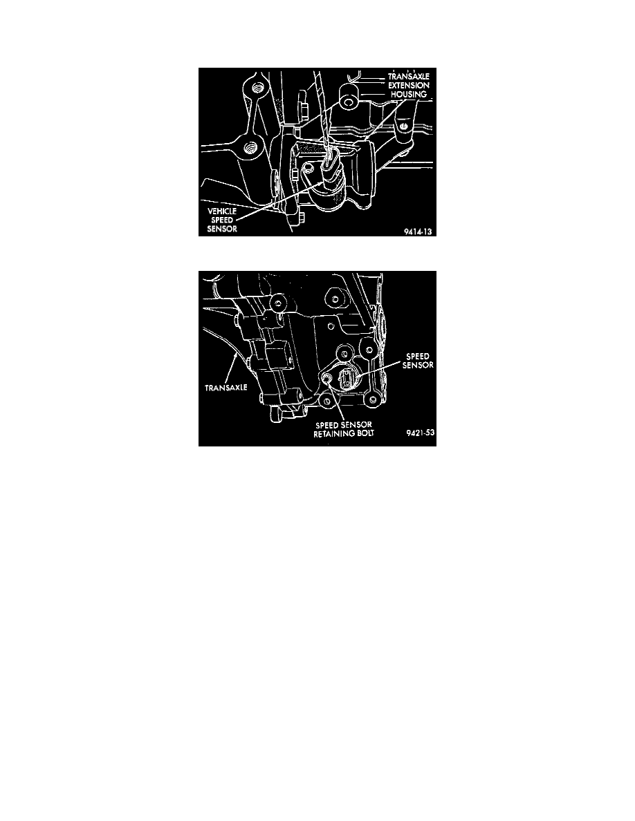
Fig. 17 Vehicle Speed Sensor -- Automatic Transmission
Fig. 18 Vehicle Speed Sensor -- Manual Transmission
PURPOSE
The sensor input is used by the PCM to determine vehicle speed and distance traveled.
OPERATION
The vehicle speed sensor generates 8 pulses per sensor revolution. These signals, in conjunction with a closed throttle signal from the throttle
position sensor, indicate a closed throttle deceleration to the PCM. Under deceleration conditions, the PCM adjusts the Idle Air Control (IAC)
motor to maintain a desired MAP value.
When the vehicle is stopped at idle, a closed throttle signal is received by the PCM (but a speed sensor signal is not received). Under idle
conditions, the PCM adjusts the IAC motor to maintain a desired engine speed.
The vehicle speed sensor signal is also used to operate:
-
Speedometer
-
Speed control
-
Daytime Running Lights (Canadian Vehicles only).
CIRCUIT OPERATION
Circuit K7 supplies 8 Volts from the Powertrain Control Module (PCM) to the Vehicle Speed Sensor (VSS). The K7 circuit connects to cavity 44
of the PCM connector.
Circuit G7 from the VSS provides an input signal to the PCM. The G7 circuit connects to cavity 66 of the PCM connector.
The PCM provides ground for the VSS signal (circuit G7) through circuit K4. Circuit K4 connects to cavity 43 of the PCM connector.