
Neon L4-2.0L VIN C (1997)
Canister Purge Solenoid: Description and Operation
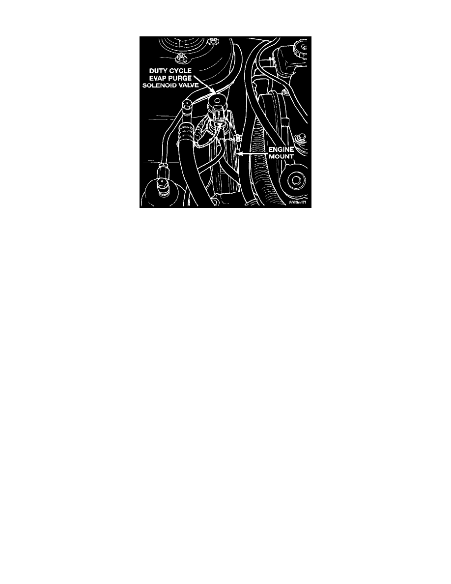
Fig. 101 Upstream Heated Oxygen Sensor Removal/Installation & EVAP Purge Solenoid Location
PURPOSE
The duty cycle EVAP purge solenoid regulates the rate of vapor flow from the EVAP canister to the throttle body. The PCM operates the
solenoid.
OPERATION
During the cold start warm-up period and the hot start time delay, the PCM does not energize the solenoid.
-
When de-energized, no vapors are purged.
When purging, the PCM energizes and de-energizes the solenoid approximately 5 or 10 times per second, depending upon operating conditions.
-
The PCM varies the vapor flow rate by changing solenoid pulse width.
-
Pulse width is the amount of time the solenoid energizes.
The solenoid attaches to a bracket which is attached to the front engine mount (Fig. 101).
CIRCUIT OPERATION
Circuit F12 supplies battery voltage to the Duty Cycle EVAP/Purge solenoid. The Powertrain Control Module (PCM) switches ground path for
the solenoid ON and OFF through circuit K52.
Circuit F12 connects to a bus bar in the fuse block fed by circuit A21. A 15 Amp fuse in the fuse block, cavity 10, protects circuit F12. Circuit F12
also connects to cavity 20 of the PCM connector.
Circuit K52 connects to cavity 68 of the PCM, and cavity 1 of the solenoid connector.
NOTE: The solenoid will not operate properly unless it is installed with the electrical connector at the top.