
Neon L4-2.0L VIN C (1997)
Whenever a reference exists to another sheet or figure, find the corresponding diagram using the Group Index, Diagrams By Sheet Number, or
Diagrams By Figure Number. The reference number for the subsequent diagram will match a listed group shown.
How to Read Wiring Diagrams
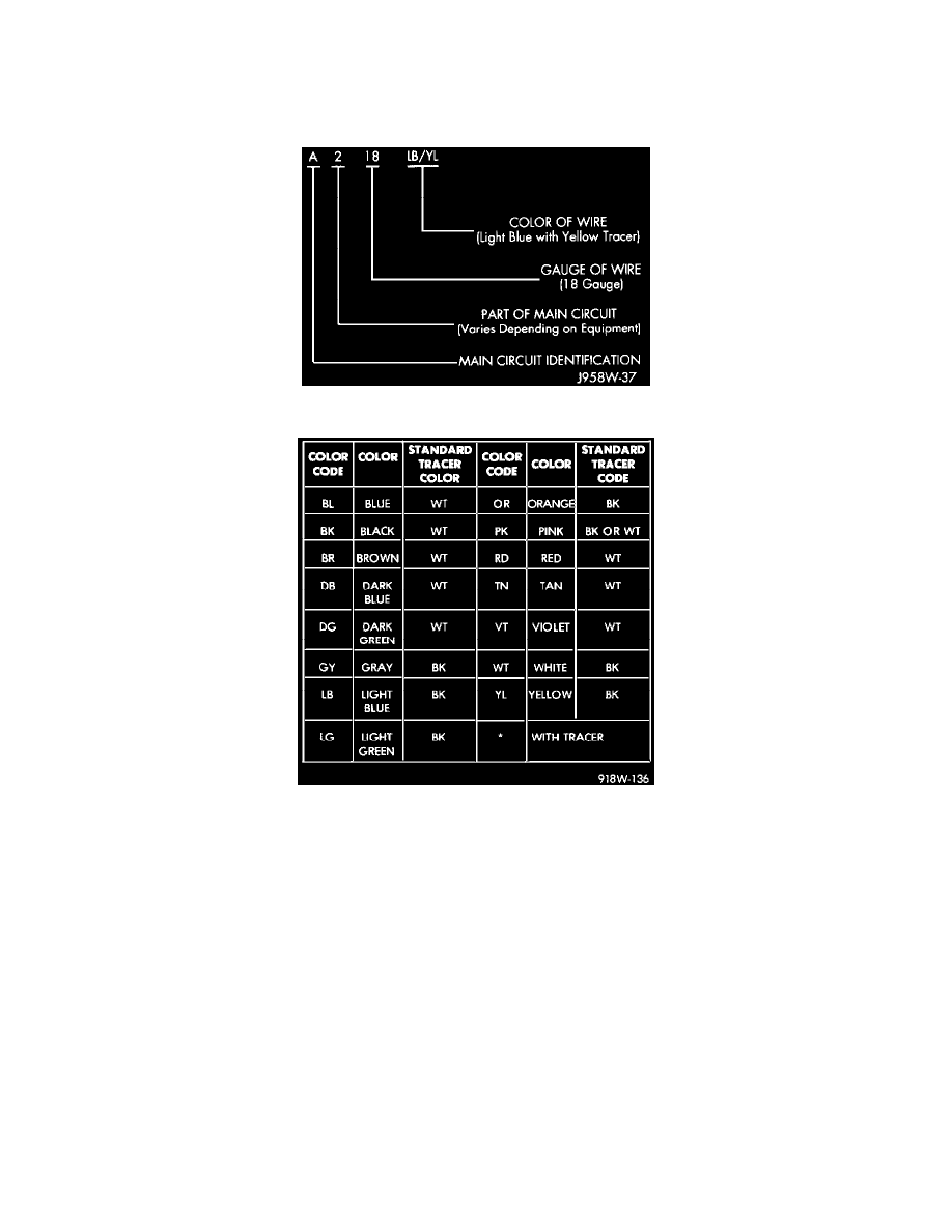
Wire Color Code Identification
Wire Color Code Chart
Each wire shown in the diagrams contains a code which identifies the main circuit, part of the main circuit, gauge of wire and color. The color is shown
as a two-letter code, which can be identified by referring to the Wire Color Code chart. If the wire has a tracer and it is a standard color, an asterisk will
follow the main wire color. If the tracer is non-standard, the main wire color will have a slash (/) after it, followed by the tracer color.
Connector and Terminal Replacement
1. Disconnect battery.
2. Disconnect the connector (that is to be repaired) from its mating half/component.
3. Cut off the existing wire connector directly behind the insulator. Remove six inches of tape from the harness.
4. Stagger cut all wires on the harness side at 1/2 inch intervals.
5. Remove 1 inch of insulation from each wire on the harness side.