
Neon L4-2.0L VIN C (1997)
Camshaft Position Sensor: Testing and Inspection
Failure to Start Test
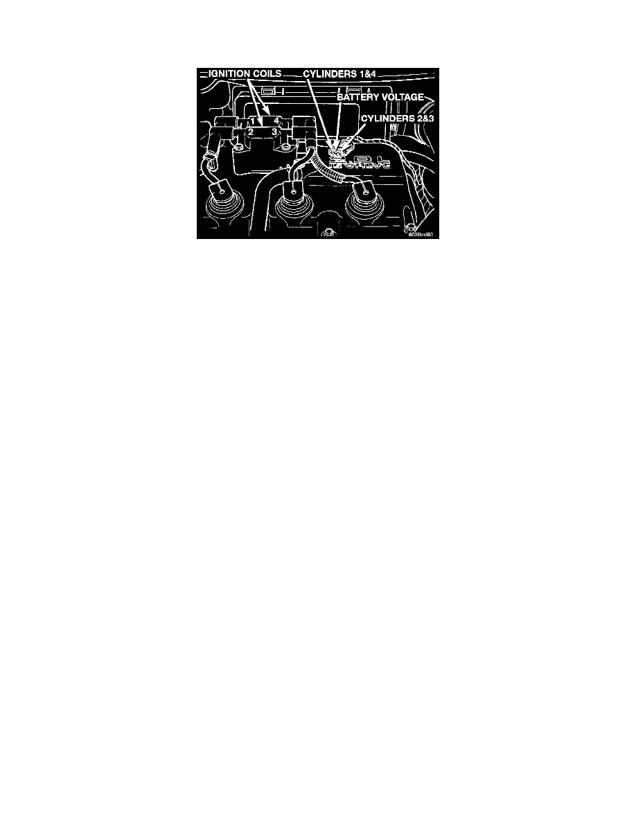
Fig.20 Ignition Coil Engine Harness Connector
This no-start test checks the camshaft position sensor and crankshaft position sensor.
Use the DRB or scan tool to test the camshaft position sensor and the sensor circuits. Refer to Diagrams/Electrical for circuit information.
The PCM supplies 8 volts to the camshaft position sensor and crankshaft position sensor through one circuit. If the 8-volt supply circuit shorts to ground,
neither sensor will produce a signal (output voltage to the PCM).
When the ignition key is turned and left in the On position, the PCM automatically energizes the auto shutdown (ASD) relay. However, the PCM
de-energizes the relay within one second because it has not received a crankshaft position sensor signal indicating engine rotation.
During cranking, the ASD relay will not energize until the PCM receives a camshaft position sensor signal. Secondly, the ASD relay remains energized
only if the PCM senses a crankshaft position sensor signal immediately after detecting the camshaft position sensor signal.
1. Check battery voltage. Voltage should be approximately 12.66 volts or higher to perform failure to start test.
2. Disconnect the harness connector from the coil pack (Fig. 20).
3. Connect a test light to the B+ (battery voltage) terminal of the coil electrical connector and ground. The B+ wire for the DIS coil is the center
terminal. Do not spread the terminal with the test light probe.
4. Turn the ignition key to the ON position.- The test light should flash ON and then OFF. Do not turn the Key to OFF position, leave it in the ON
position.
a. If the test light flashes momentarily, the PCM grounded the ASD relay. Proceed to step 5.
b. If the test light did not flash, the ASD relay did not energize. The cause is either the relay or one of the relay circuits. Use the DRB or scan tool
to test the ASD relay and circuits. Check for codes and follow procedures. SEE Computers and Control Systems/Testing and Inspection/
Diagnostic Charts. Refer to Diagrams/Electrical for circuit information.
5. Crank the engine. (If the key was placed in the OFF position after step 4, place the key in the ON position before cranking. Wait for the test light
to flash once, then crank the engine.)
6. If the test light momentarily flashes during cranking, the PCM is not receiving a crankshaft position sensor signal.
7. If the test light did not flash during cranking, unplug the crankshaft position sensor connector. Turn the ignition key to the off position. Turn the
key to the ON position, wait for the test light to momentarily flash once, then crank the engine. If the test light momentarily flashes, the crankshaft
position sensor is shorted and must be replaced. If the light did not flash, the cause of the no-start is in either the crankshaft position sensor/
camshaft position sensor 8 volt supply circuit, or the camshaft position sensor output or ground circuits.