
Neon L4-2.0L VIN C (1997)
18.
Install the park brake lever assembly.
19.
Tighten the four (4) ACM nuts and the remaining park brake lever nut to 115 in-lbs (12.5 N.m).
20.
Connect the park brake lever switch electrical connector and attach the wiring clips to the ACM bracket.
21.
Install both rear park brake cables into the equalizer.
22.
Pull the park brake lever handle all the way up.
23.
Firmly grasp the park brake lever locking pin (drill bit) and quickly remove it from the mechanism.
24.
Cycle the park brake lever once to position the park brake cables.
25.
Make sure that the park brake lever is fully raised and then install the center console assembly.
26.
Install the front two (2) center console attaching screws located near the cup holders (Figure 1).
27.
Install the two (2) screws at the bottom of the storage bin (Figure 2).
28.
Install the two (2) outer lower console bracket bolts on each side of the storage bin and then install the bolt covers.
29.
For Manual Transmission Equipped Vehicles: Install the shifter knob and fastener.
30.
Connect the DRB III, turn the ignition switch to the ON position and then exit the vehicle with the DRB III.
31.
Reconnect the negative battery cable and then watch the airbag light in the instrument cluster, it should light for about 6-8 seconds and then go out.
32.
With the DRB III, verify that no system diagnostic codes have been set.
NOTE:
If the airbag warning lamp fails to light or the light stays on, or the DRB displays a diagnostic code, a system malfunction exists. Diagnose and repair
the condition following normal service procedures.
Service Procedure For Dakota (AN) Vehicles:
1.
With the ignition key in the OFF position, disconnect and isolate the negative battery cable. WAIT TWO (2) MINUTES FOR THE SYSTEM
CAPACITOR TO DISCHARGE BEFORE CONTINUING.
Note:
To enhance customer satisfaction, remember to record all radio settings before disconnecting the battery and to reset all electronic memory (clock,
radio settings, etc.) when you have completed the service procedure.
2.
Pull back the floor carpet from the area around the center instrument panel support.
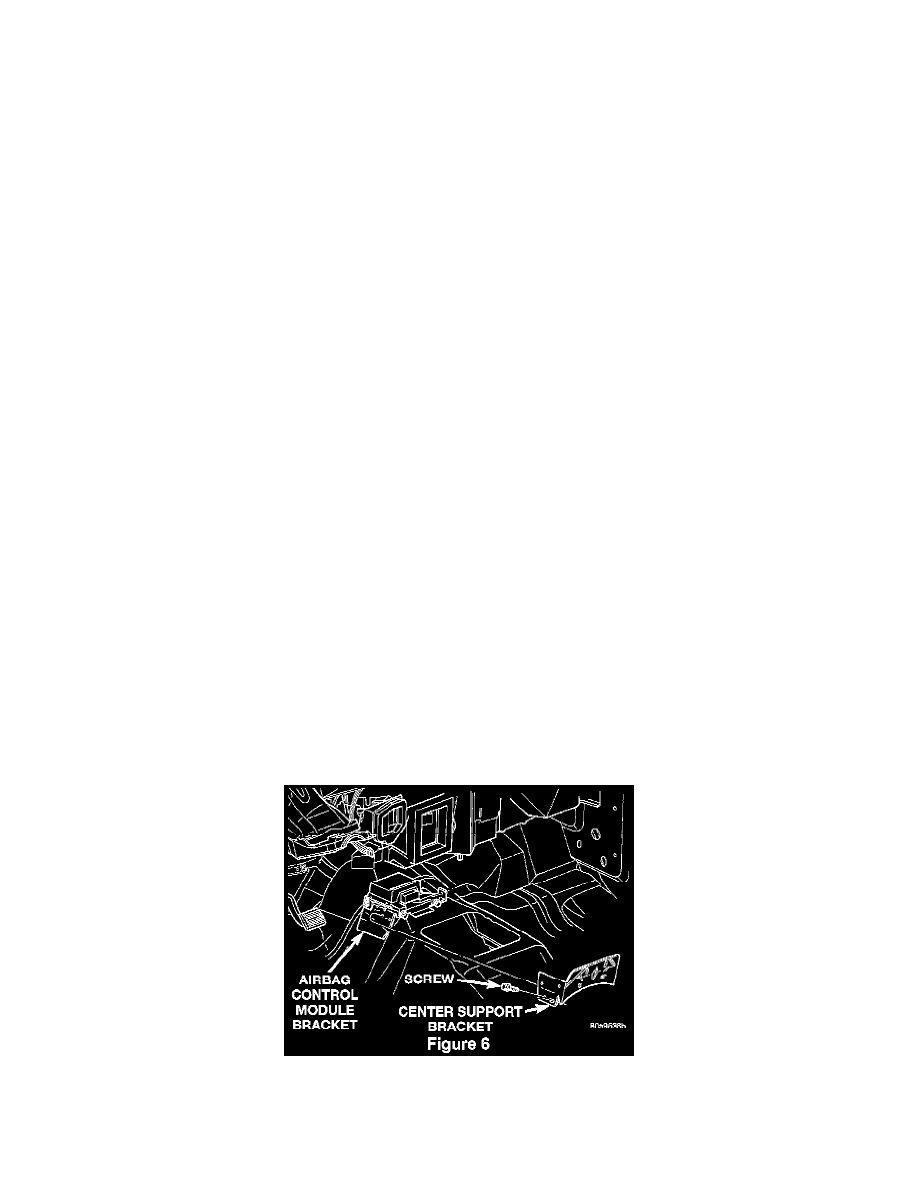
3.
Remove the two (2) front center support bracket screws (Figure 6).
4.
Remove the two (2) left side and one (1) right side support bracket screws (Figure 6).