
PB 150 V8-318 5.2L VIN T 2-BBL (1983)
Brake Proportioning/Combination Valve: Description and Operation
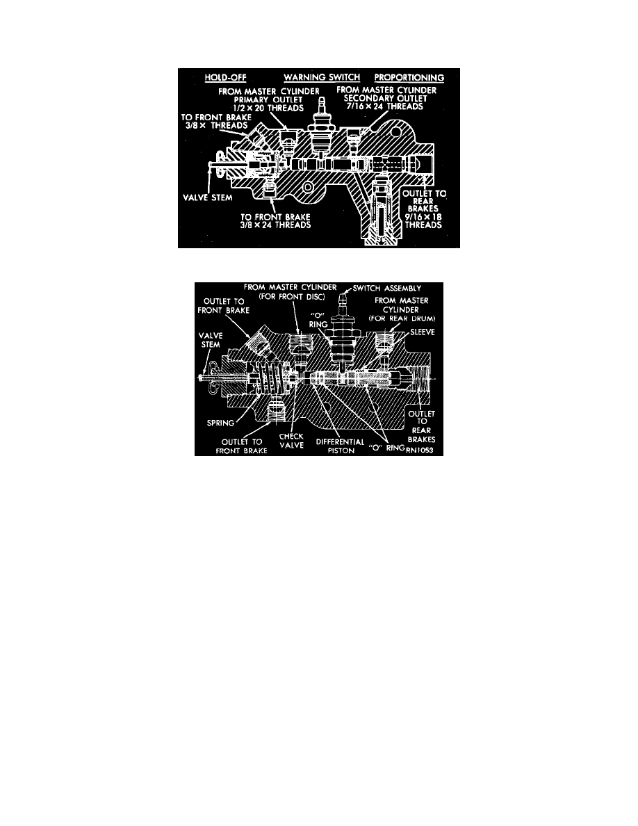
Hold-Off Valve
Fig. 23 Type 1, Combination Valve
Fig 2 Brake Warning Switch / Hold Off Valve (Cut Away View)
NOTE: Some vehicles incorporate a hold-off valve, usually in combination with the brake warning switch. This valve is part of a combination valve.
See Application and ID.
PURPOSE
Hold-off valves are used because of different braking characteristics between disc and drum brakes. This valve holds off hydraulic pressure to the
front disc brakes to a given pressure range to allow the rear drum brake shoes to overcome the return springs and begin to contact drums.
-
With disc brakes, brake application is immediate and braking response is directly proportional to pedal effort.
-
Drum brake response occurs after piston travel, return spring stretch, and shoe contact with the drum. After contact self energizing tends to
multiply pedal effort.
-
This action helps prevent locking of the front brakes on icy surfaces under light braking conditions.
-
This valve has no effect on front brake pressure during hard stopping.
OPERATION
The hold-off valve section of the combination valve holds off pressure to the front disc brakes to allow the rear drum brake shoes to overcome the
return springs and begin to contact the drums.
-
This valve keeps the output pressure to the front brakes in the 3 to 30 PSI range until the hold-off pressure in the hold off valve reaches (117
PSI) at this point the valve allows full output pressure to reach the front brakes.
-
This helps to prevent the front brakes from locking under light pedal application when driving on icy surfaces.
NOTE: The hold off valve has no effect on front brake pressure during hard stops.