
PB 150 V8-318 5.2L VIN T 2-BBL (1983)
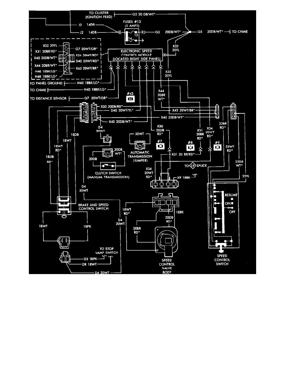
Fig. 10 Speed control wiring diagram. 1986 Mini-Vans/Wagons
Rear Wheel Drive Models
1. Check fuse for continuity.
2. Disconnect four wire electrical connector at steering column.
3. Connect a suitable 12 volt power source to black wire terminal of switch harness connector.
4. Attach one lead of a suitable test lamp to ground, then attach the second lead to yellow wire terminal. Test lamp should illuminate with speed
control switch in "on" position. Test lamp should be off when set button is depressed, or when speed control switch is in "off" position.
5. Attach test lamp lead to dark blue wire. Test lamp should illuminate with slide switch in "on" position and be off with slide switch in "off"
position.
6. Attach test lead to white wire. Test lamp should be off with slide switch in "on" position, illuminate when set button is depressed, and be off when
switch is released. Test lamp should illuminate when slide switch is moved to "Resume" position, and go off when slide switch is released.
7. Replace speed control switch if test lamp does not respond as indicated.