
PB 150 V8-318 5.2L VIN T 2-BBL (1983)
Camshaft: Service and Repair
NOTE: When removing camshaft or bearings, it is recommended that the engine be removed from chassis.
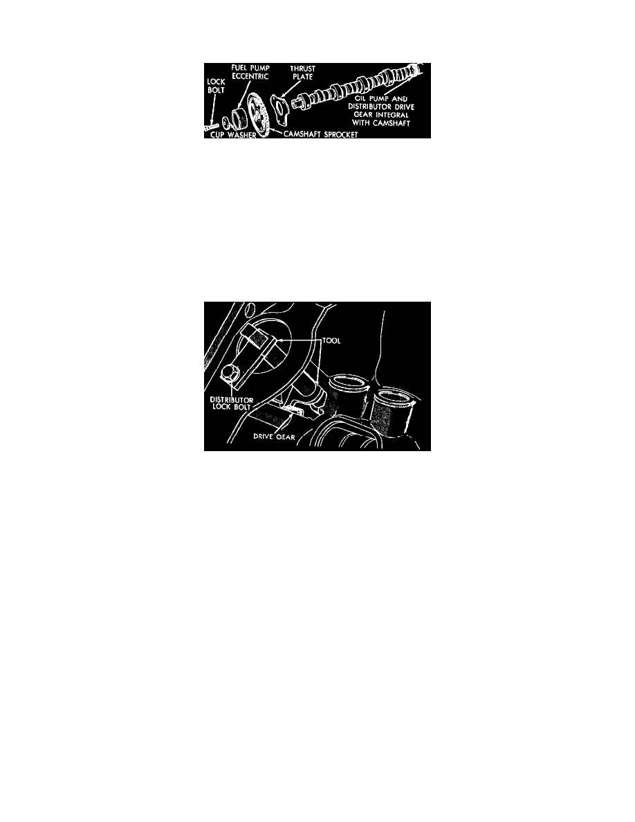
Fig. 17 Camshaft assembly. V8-318 (5.2L) & V8-360 (5.9L)
V8-318 (5.2L) & V8-360 5.9L
Removal
1.
Remove intake manifold, cylinder head covers, timing chain cover and timing chain.
2.
Remove rocker arm and shaft assemblies.
3.
Remove pushrods and lifters using suitable tool. Identify lifters to ensure correct position during installation.
4.
Remove distributor, then lift out oil pump and distributor driveshaft.
5.
Remove camshaft thrust plate noting location of oil tab.
6.
Install long bolt into front of camshaft to facilitate removal, then remove camshaft from engine, Fig. 17.
Fig. 18 Install camshaft holding tool
Installation
1.
Lubricate camshaft lobes and bearing journals, then install camshaft within two inches of final position in cylinder block.
2.
Install tool No. C-3509 as shown in Fig. 18.
3.
Hold tool in position with distributor lock plate screw. Tool should remain installed until camshaft, crankshaft sprockets and timing chain
have been installed.
4.
Install camshaft thrust plate and chain oil tab attaching screws, ensuring tang enters lower right hole in thrust plate, then torque attaching screws to
210 inch lbs. Top edge of tab should be flat against thrust plate in order to catch oil for chain lubrication.
5.
Install timing chain, refer to ``Timing Gears Or Chain'' procedure.
6.
Install fuel pump eccentric, cup washer and camshaft bolt. Torque bolt to 35 ft. lbs.
7.
Reverse remaining procedure to assemble.
V8-446 (7.3L)
1.
Remove oil pump and distributor.
2.
Remove valve lifters, water pump, crankshaft pulley and damper, then the timing case cover.
3.
Remove camshaft thrust flange attaching bolts, then the camshaft. Use caution when handling camshaft assembly to prevent chipping
distributor gear teeth.
4.
Reverse procedure to install. To align timing marks refer to ``Timing Gears Or Chain, Replace'' procedure.