
PB 150 V8-318 5.2L VIN T 2-BBL (1983)
Rocker Arm Assembly: Service and Repair
When disassembling rocker arms, place all parts on the workbench in their proper sequence to ensure correct assembly.
Clean all sludge and gum formation from the inside and outside of the shafts. Clean oil holes and passages in the rocker arms and shafts. Inspect the
shafts for wear.
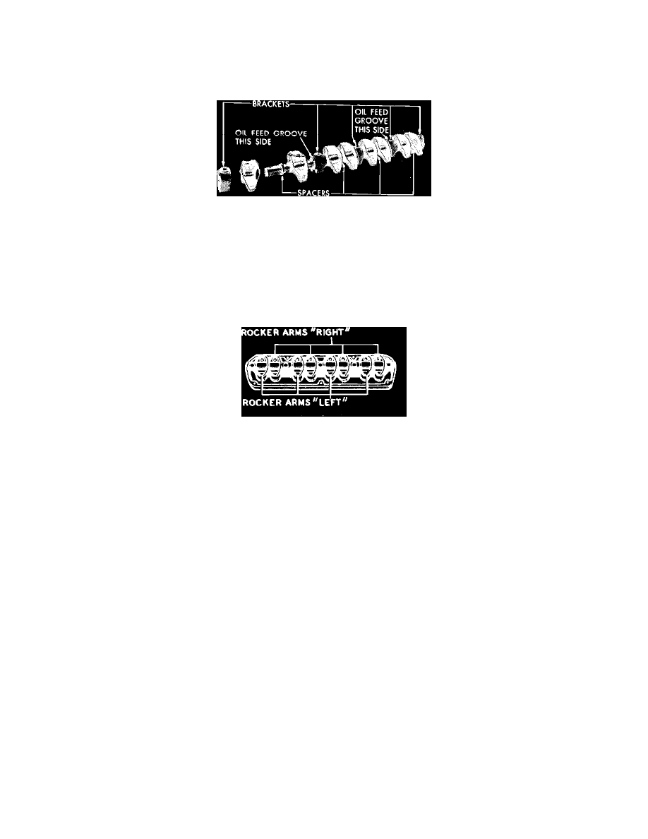
Fig. 8 Rocker arm and shaft assembly installed. V8-318 (5.2L) & V8-360 (5.9L)
V8-318 (5.2L) & V8-360 (5.9L)
To provide proper lubrication of the rocker arms, the rocker shafts have a small notch machined at one end. Install rocker arm and shaft assemblies
with notch on end of rocker shaft pointing to center line of engine and toward front of engine on the left bank and to the rear on the right bank. If
rocker arms are removed from shaft, care must be taken to ensure proper reassembly. Some exhaust rocker arms have a relieved area on the underside
for rotator clearance. Refer to Fig. 8 for proper positioning of rocker arms. Note placement of long stamped steel retainers in the number two and four
positions between the rocker arms.
Fig. 9 Rocker arm and shaft assembly. V8-446 (7.3L)
V8-446 (7.3L)
The rocker arms on these engines are individually mounted and are retained by flange head bolts and pivot balls. Install the rocker arm components in
original position, Fig. 9.
Inspect the pivot surfaces of the rocker arms and pivot balls for signs of scuffing, pitting or excessive wear. Inspect the valve stem contact surface of
the rocker arms for pitting. Replace any component found unsatisfactory.