
PB 150 V8-318 5.2L VIN T 2-BBL (1983)
Intake Manifold: Service and Repair
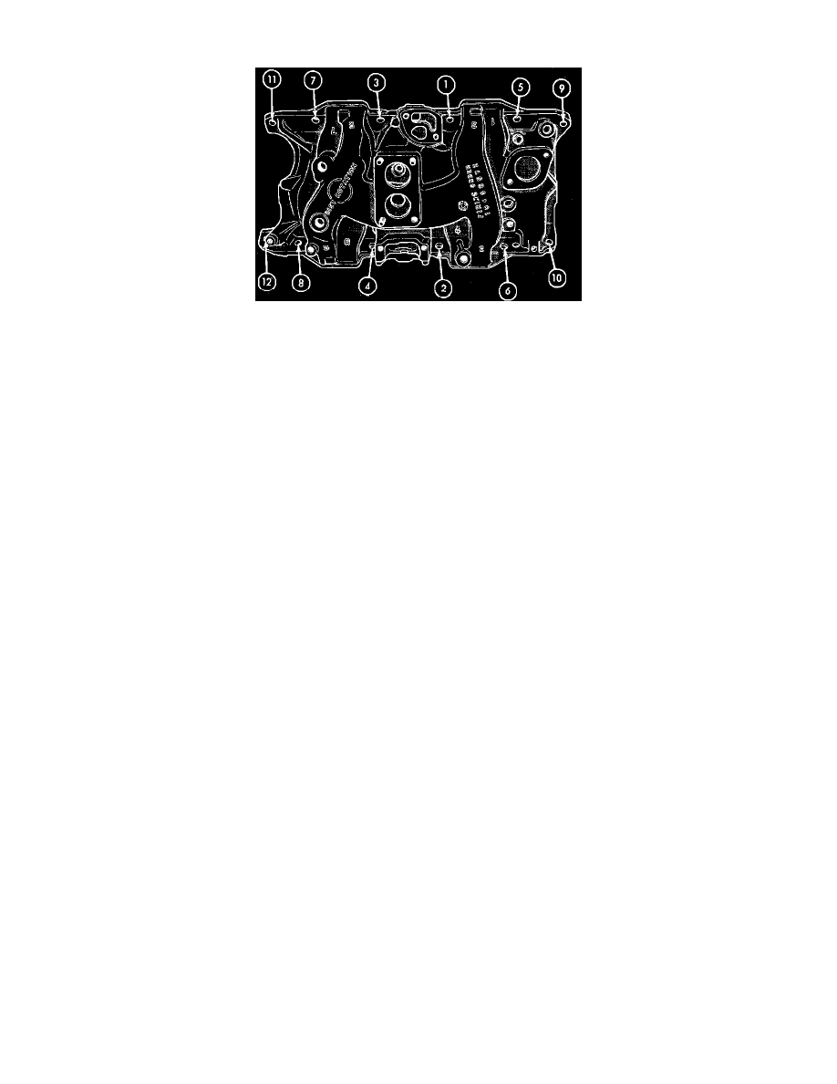
Fig. 2 Intake manifold tightening sequence. V8-318 (5.2L) & V8-360 (5.9L)
V8-318 (5.2L) & V8-360 (5.9L)
1. Disconnect battery ground cable, then drain cooling system.
2. Remove alternator, carburetor air cleaner and fuel line, then disconnect accelerator linkage.
3. Remove vacuum control hose between carburetor and distributor.
4. Remove distributor cap with wires attached, then disconnect coil wires, heat indicator sending unit wire, heater hoses and bypass hose.
5. Remove closed ventilation system, evaporation control system and cylinder head covers.
6. Remove intake manifold attaching bolts, then the intake manifold.
7. Reverse procedure to install, noting the following:
a. On V8-318 (5.2L) engines, coat intake manifold side gaskets with suitable sealer.
b. On V8-360 (5.9L) engines, do not use any sealer on side composition gaskets.
c. Apply a thin coating of suitable sealer to the intake manifold front and rear gaskets and cylinder block gasket surface.
d. When installing front and rear gaskets, ensure center holes in gasket engage dowels in block and end holes in seals are locked into tangs of
head gasket.
e. Place a drop of suitable sealer onto each of the four manifold to cylinder head gasket corners.
f.
Tighten intake manifold bolts in sequence shown in Fig. 2.