
PB 150 V8-318 5.2L VIN T 2-BBL (1983)
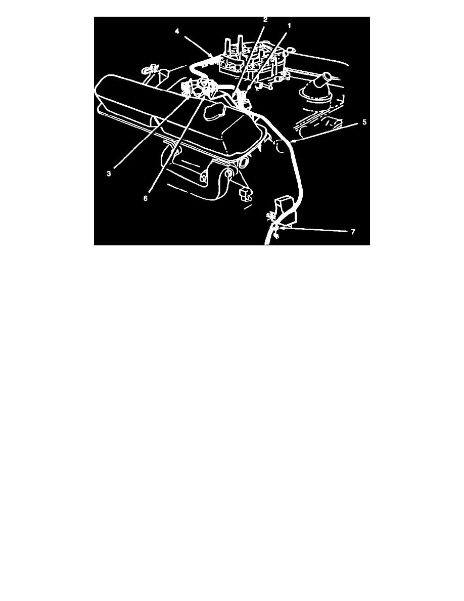
FIGURE 5FUEL PRESSURE REGULATOR INSTALLATION
4.
Install new tube, PN 4418008, from the regulator outlet to the carburetor inlet. Install new tube, PN 4418014, from the reservoir outlet hose
to the regulator inlet (Figure 5). Be sure that the tube passes through the clip mounted on the mechanical fuel pump attachment bolt. Slightly
compress clip to secure tube away from any possible interference with nearby components.
5.
Install clamp, PN 6500651, as shown in Figure 5 (filter outlet hose-to-regulator inlet tube). Rotate clamp so that it is not in contact with any
other surface. Torque to 10 inch pounds.
For all models except those equipped with dual air conditioning units, without electrically heated rear window defroster and with 60 amp alternator:
6.
Reconnect battery. Check wire and hose routing, start the engine, and inspect the entire system for fuel leaks.
7.
Reinstall engine cover.
G.Vehicles Equipped With Dual Air Conditioning Units, Without Electrically Heated Rear Defroster,
and With 60 Amp Alternator. I