
PB 150 V8-318 5.2L VIN T 2-BBL (1983)
Temperature Warning Indicator - A/T: Testing and Inspection
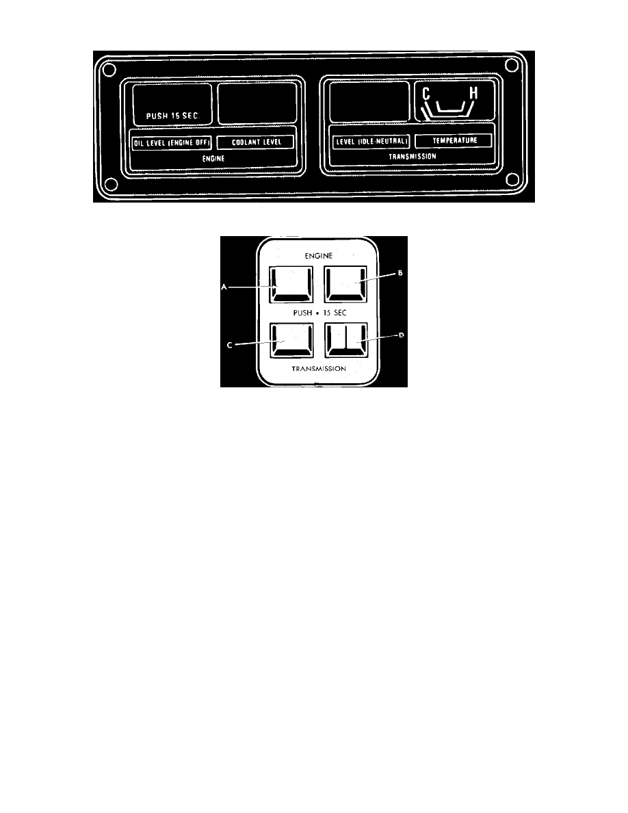
Fig. 3 Recreational vehicle sensor package instrument cluster. 1980
Fig. 4 Recreational vehicle sensor package instrument cluster. 1981-82
The recreational vehicle sensor package consists of a separate instrument cluster, Figs. 3 and 4, which allows the driver to monitor the following
conditions: engine oil level, engine coolant level, transmission fluid level and transmission fluid temperature.
TROUBLESHOOTING
VOLTAGE LIMITER TEST
1. Connect voltmeter between temperature sending unit (locating in fitting in bottom radiator tank) and a suitable ground. Do not disconnect
electrical connector from sending unit.
2. Turn ignition switch to On position and observe voltmeter.
3. If voltmeter needle fluctuates, the voltage limiter is operating properly.
4. If voltmeter does not fluctuate, replace voltage limiter. The voltage limiter is located on the sensor panel. To gain access to the limiter,
remove panel and unsnap the back cover.
TEMPERATURE GAUGE TEST
1. Disconnect electrical connector from temperature sending unit in lower radiator tank.
2. Connect tester No. C-3826 or equivalent between temperature sending unit and a suitable ground.
3. Move tester pointer to ``C'' position, then turn ignition switch On and observe temperature gauge. Temperature gauge should read within 1/8 inch
of ``C''.
4. Move tester pointer to ``M'' position. Temperature gauge should now advance to normal range left of 1/2 position on dial.
5. Move tester pointer to ``H'' position. Temperature gauge should now advance to ``H'' position on dial.
6. If temperature gauge responds to tests described in steps 3, 4 and 5, but does not operate when sending unit electrical connector is attached, the
sending unit is defective and should be replaced.
7. If temperature gauge does not respond to tests described in steps 3, 4 and 5, check for loose connections, broken wire, open printed circuit or
faulty gauge.
OIL LEVEL PUSH BUTTON SWITCH
1. Inspect switch for poor solder connections and repair or replace as necessary.
2. Test each circuit for continuity using an ohmmeter or test lamp. If any open circuits are found, the switch should be replaced. To replace switch,