
PB 150 V8-318 5.2L VIN T 2-BBL (1983)
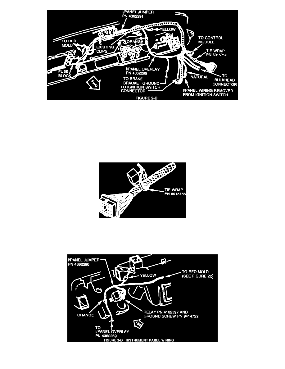
FIGURE 2D - INSTRUMENT PANEL WIRING
4.
Disconnect the arced grey 7-way ignition switch connectors and remove the orange wire from the instrument panel side (Figure 2-C).
Install the extracted terminal (orange wire) into the natural colored 1-way connector supplied with instrument panel overlay harness, PN
4362289.
Install the bare terminal (orange wire) from the instrument panel overlay harness, PN 4362289, into the vacated cavity in the ignition switch
connector. Reconnect the natural colored 1-way connectors supplied with the instrument panel overlay harness, PN 4362289, and reconnect
the ignition switch connectors (Figure 2-C and 2-D).
FIGURE 2E - TYPICAL CONTROL MODULE MOUNTING
5.
Connect the control (auto shut-down) module, PN 5226640, to the natural colored 8-way connector from instrument panel overlay harness,
PN 4362289. Secure the module onto the main instrument panel wiring harness with a tie wrap, PN 6015756, close to the bulkhead connector
(Figure 2-E).
INSTRUMENT PANEL WIRING