
PB 150 V8-318 5.2L VIN T 2-BBL (1983)
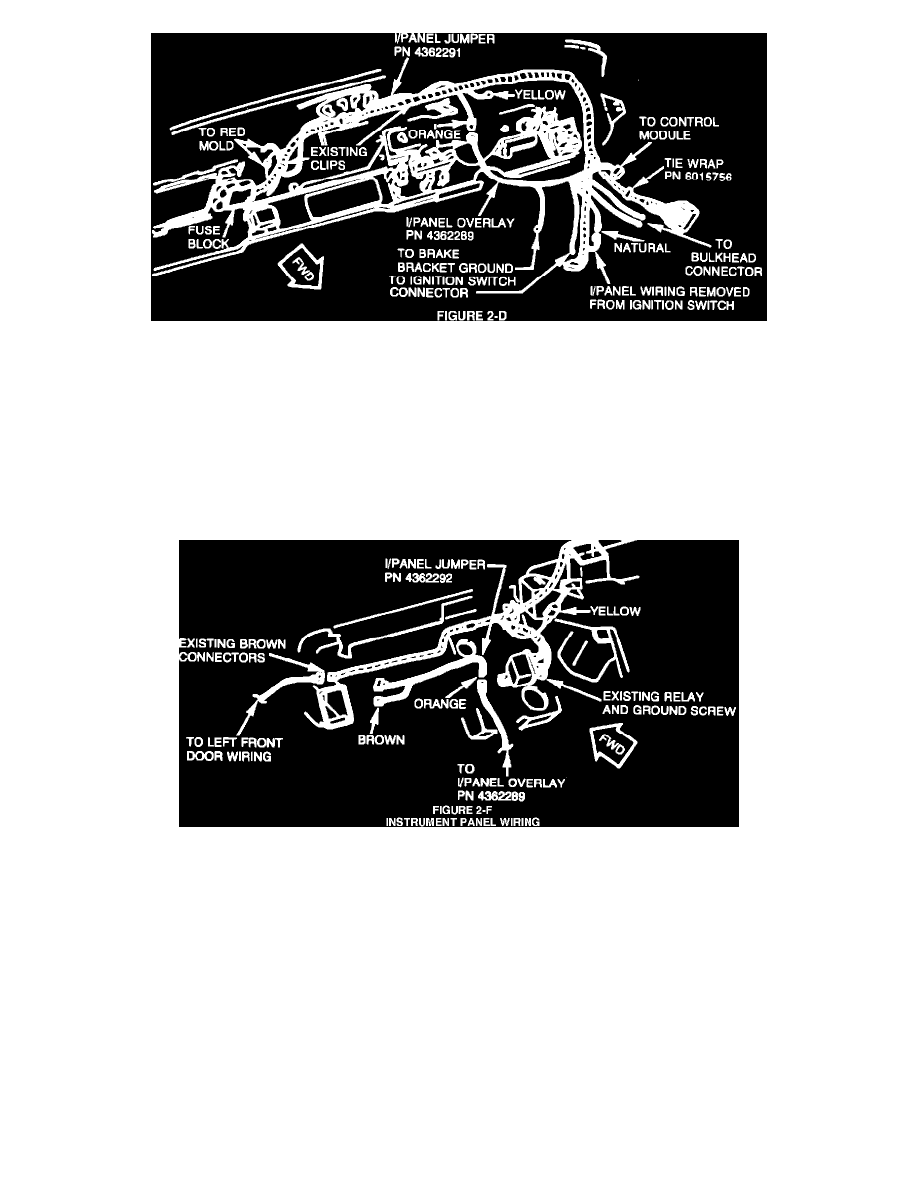
FIGURE 2D - INSTRUMENT PANEL WIRING
b.
Route instrument panel jumper harness, PN 4362291, from the back of the brake bracket to the existing 3-way red molded connector.
Secure by using existing wiring clips (Figure 2-D).
c.
Insert the bare bullet terminal (black with white tracer wire) from instrument panel jumper harness, PN 4362291, into the existing
3-way red molded connector from the main instrument panel wiring harness (Figure 2-D).
d.
Mate the orange colored 1-way connector from instrument panel jumper harness, PN 4362291, to the orange colored 1-way connector
from the instrument panel overlay harness, PN 4362289 (Figure 2-D).
e.
Reinstall instrument panel hood and bezel assembly and install radio.
FIGURE 2F - INSTRUMENT PANEL WIRING
7.
With Auxiliary Air Conditioning and/or Heater and Power Windows - Jumper Harness PN 4362292
a.
Disconnect from each other, the two existing brown colored 1-way connectors located near the left instrument panel vent (Figure 2-F).
Reconnect these two brown colored 1-way connectors to the two brown colored 1-way connectors from instrument panel jumper
harness, PN 4362292 (Figure 2-F).
b.
Mate the orange colored 1-way connector from the instrument panel jumper harness, PN 4362292, to the orange colored 1-way
connector from instrument panel overlay harness, PN 4362289 (Figure 2-F).