
PB 150 V8-318 5.2L VIN T 2-BBL (1983)
INSTRUMENT PANEL WIRING
e.
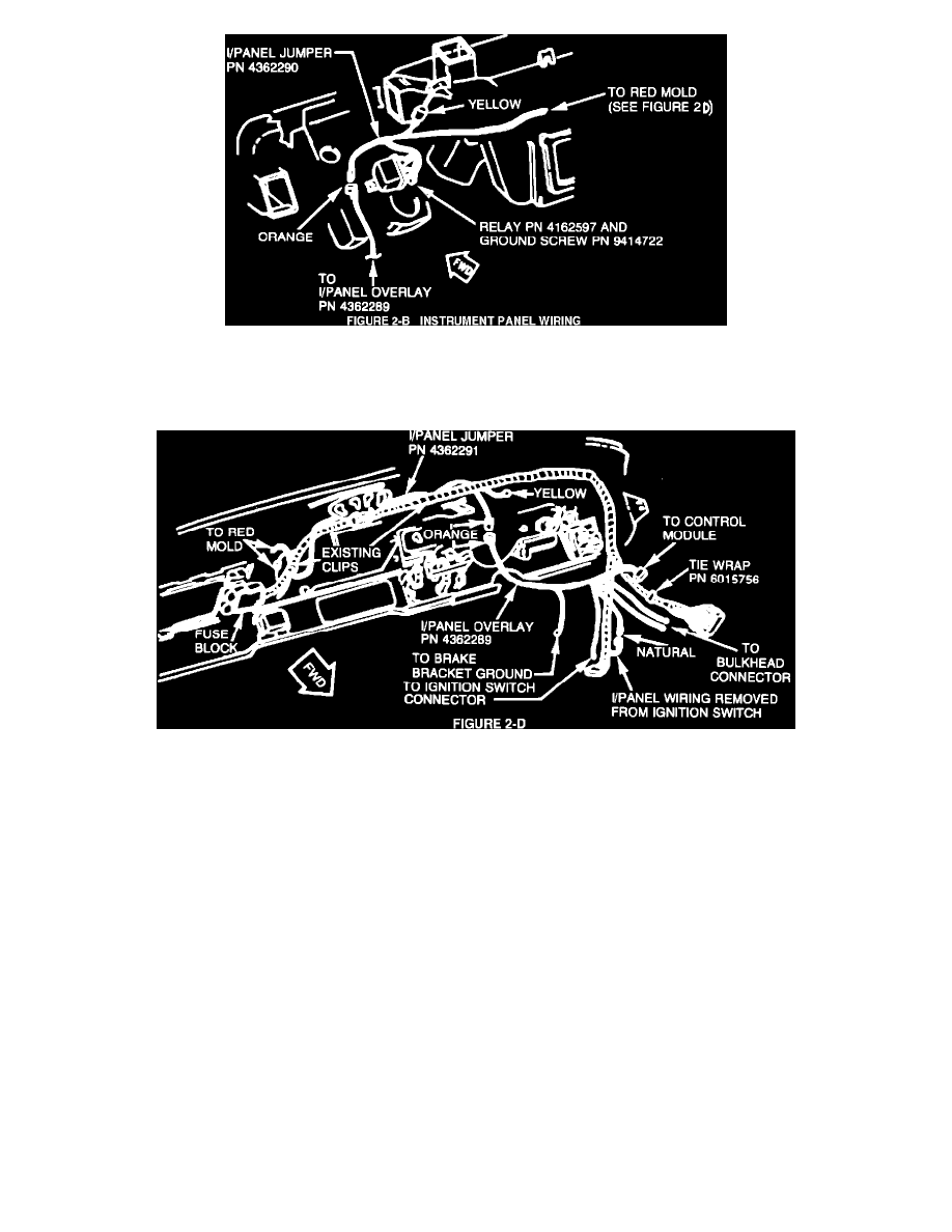
Insert bare bullet terminal (red wire) from instrument panel relay harness, PN 4362290, into the existing 3-way yellow molded
connector from the main instrument panel wiring harness (Figure 2-B).
FIGURE 2D - INSTRUMENT PANEL WIRING
f.
Mate the orange colored 1-way connector from instrument panel relay harness, PN 4362290, to the colored 1-way connector from the
instrument panel overlay harness, PN 4362289 (Figure 2-D).
g.
Install the instrument panel left lower trim panel, instrument panel hood, bezel assembly and radio.
C.In-Tank Fuel Pump Installation
1.
Remove the fuel tank gauge unit from the fuel tank per the service manual procedure and discard. Install the new seal and
gauge/pump unit from the applicable kit. Use extreme caution to protect the float and gauge assembly during installation into the
fuel tank.
2.
With the fuel tank partially raised, connect the fuel tank vent hose, fuel return, and fuel supply hoses. Secure the hoses with the
hose clamps provided.
3.
Feed red and yellow molds of body wiring harness, PN 4362293, through slot in the crossmember. Remove existing screw for
gauge unit ground. Install eyelet terminal of harness, PN 4362293 (and ground eyelet terminal of 36 gallon tank gauge/pump
unit) and torque ground screw to 36 inch pounds.
CAUTION:
GROUND SCREW MUST BE TIGHTENED SECURELY TO OPERATE ELECTRIC PUMP AND
GAUGE UNIT.