
PB 150 V8-318 5.2L VIN T 2-BBL (1983)
Charge Temperature Sensor: Description and Operation
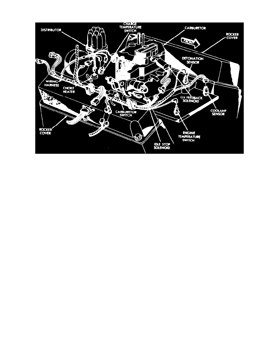
Fig. 4 Switches & sensors location. V8 engine
The CTS, Fig. 4, is used on eight cylinder engines and is located in the intake manifold No. 8 runner on eight cylinder engines. When the incoming air
fuel mixture is below 60° F., the CTS will close, allowing no EGR timer function, no EGR valve operation and the air injection directed upstream into
the exhaust manifold. When incoming air-fuel mixture is above 60° F., the CTS will open allowing EGR timer to expire, the EGR valve to operate and
air injection switched downstream into the exhaust system.