
PB 150 V8-318 5.2L VIN T 2-BBL (1983)
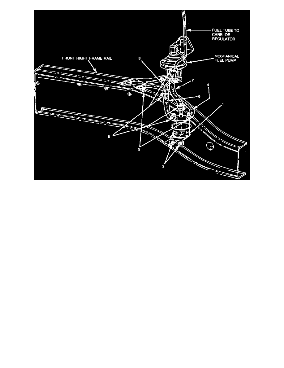
FIGURE 4B - Mounting Fuel Resevoir/Filter
2.
Install supplied fuel reservoir/filter, PN 4418012, using two (2) self-tapping screws, PN 6022777 (Figure 4-B). Screws must be tightened to
95 +/- 10 inch pounds.
NOTE:
RUBBER SPLASH SHIELD MAY HAVE TO BE CUT OUT AROUND FUEL RESERVOIR.
3.
Remove and discard the fuel pump outlet tube, return hose, and fuel filter with rubber hoses and clamps. Install the fuel pump-to-reservoir
tube, PN 4306968 (Figure 4-B).
4.
Install return hose assembly, PN 4418006, from the fuel reservoir return nipple to the chassis tube, and clamp with PN 6500650 at each end
(Figure 4-B).
5.
Slide both 6" pieces of convolute sleeve, PN 4279993, over each 5/16" x 8" hose, PN 42O3576.