
PB 150 V8-318 5.2L VIN T 2-BBL (1983)
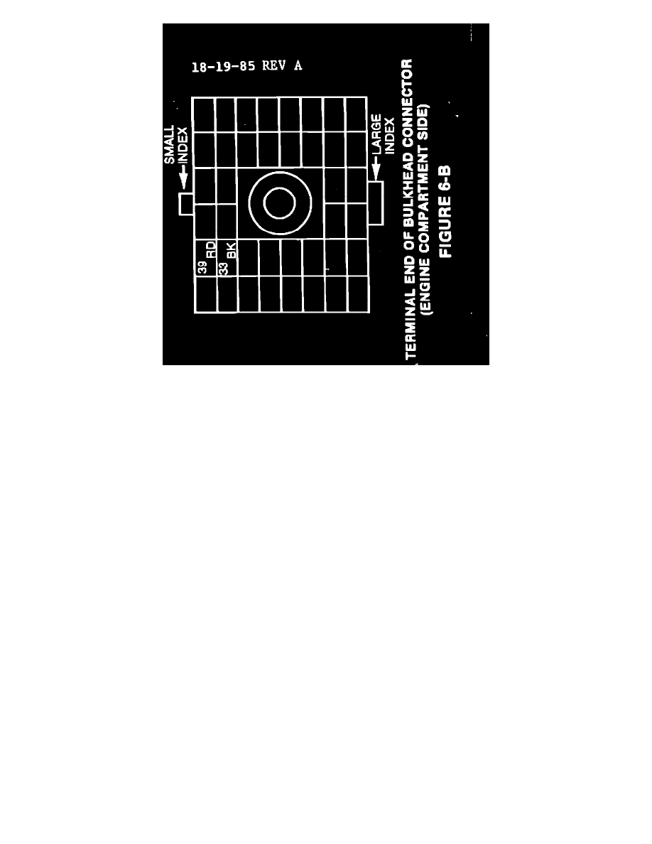
FIGURE 6-B - TERMINAL END OF BULKHEAD CONNECTOR(ENGINE COMPARTMENT SIDE)
5.
Beginning at the bulkhead, route and connect the wiring assembly, PN 4362343, as shown in Figure 6-A. Use the existing clip for main
harness and tie wrap with three (3) tie wraps, PN 6015756. Insert the two bare terminals from alternator overlay wiring harness, PN 4362343,
as shown in Figure 6-B as follows:
NOTE:
THE 4362343 ALTERNATOR OVERLAY HARNESS WAS MANUFACTURED WITH THE RED AND BLACK WIRES
REVERSED. THEREFORE, IT WILL BE NECESSARY TO INSTALL THE BLACK WIRE (LABELED RED) INTO CAVITY #39
(RED WIRE PREVIOUSLY REMOVED), AND THE RED WIRE (LABELED BLACK) INTO CAVITY #33 (BLACK WIRE
PREVIOUSLY REMOVED). FAILURE TO REVERSE THESE TWO WIRES WILL RESULT IN THE AMMETER SHOWING THE
OPPOSITE CHARGE INDICATION.
a.
Red wire into cavity #33 (ammeter) - (labeled as black wire).
b.
Black wire into cavity #39 (ammeter) - (labeled as red wire).
6.
Install wiring assembly, PN 4362343, alternator output terminal to new 78 amp alternator.