
PB 150 V8-318 5.2L VIN T 2-BBL (1983)
pulley cover. Between the engine and the vacuum harness loop the hose approximately 2.5" from the vacuum reducer valve and connect to the
remaining nipple.
10.
Tape the four nylon-vacuum tubes together at the edge of the in-line connector.
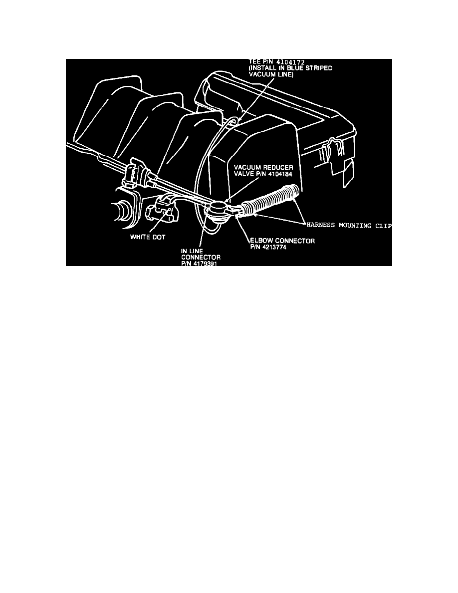
FIGURE 2
See Figure 2 attached
INSTALLATION OF A VACUUM REDUCER VALVE ON A 3.7L ENGINE
VACUUM REDUCER INSTALLATION PACKAGE PN 4293798
PARTS REQUIRED
PART NUMBER
1 - Vacuum Reducer Valve
2 - In-Line Connector
4104184
1 - Tee
4241296
4104172
INSTALLATION PROCEDURE
1.
Cut two 1.5" sections of 3/16" hose (use Bulk Stock PN 3780507) and install on the white nipples of the Vacuum Reducer Valve, PN 4114184.
Install the in-line connectors on the hoses with the large end to the hose.
2.
Cut one 8" length of 3/16" hose and install on the remaining nipple of the vacuum reducer valve. Install the Tee, PN 4104172, at the other end on
the 8" hose.
3.
Locate the orange striped hose connecting the vacuum amplifier in the vacuum solenoid. Cut this hose 2.5" from the solenoid and install the tee of
the vacuum reducer subassembly.
4.
Locate the vacuum hose, harness bundle running along the inside of the valve cover. Cut the yellow striped hose midway between the two tape
wraps and install the vacuum reducer sub-assembly.