
PB 150 V8-318 5.2L VIN T 2-BBL (1983)
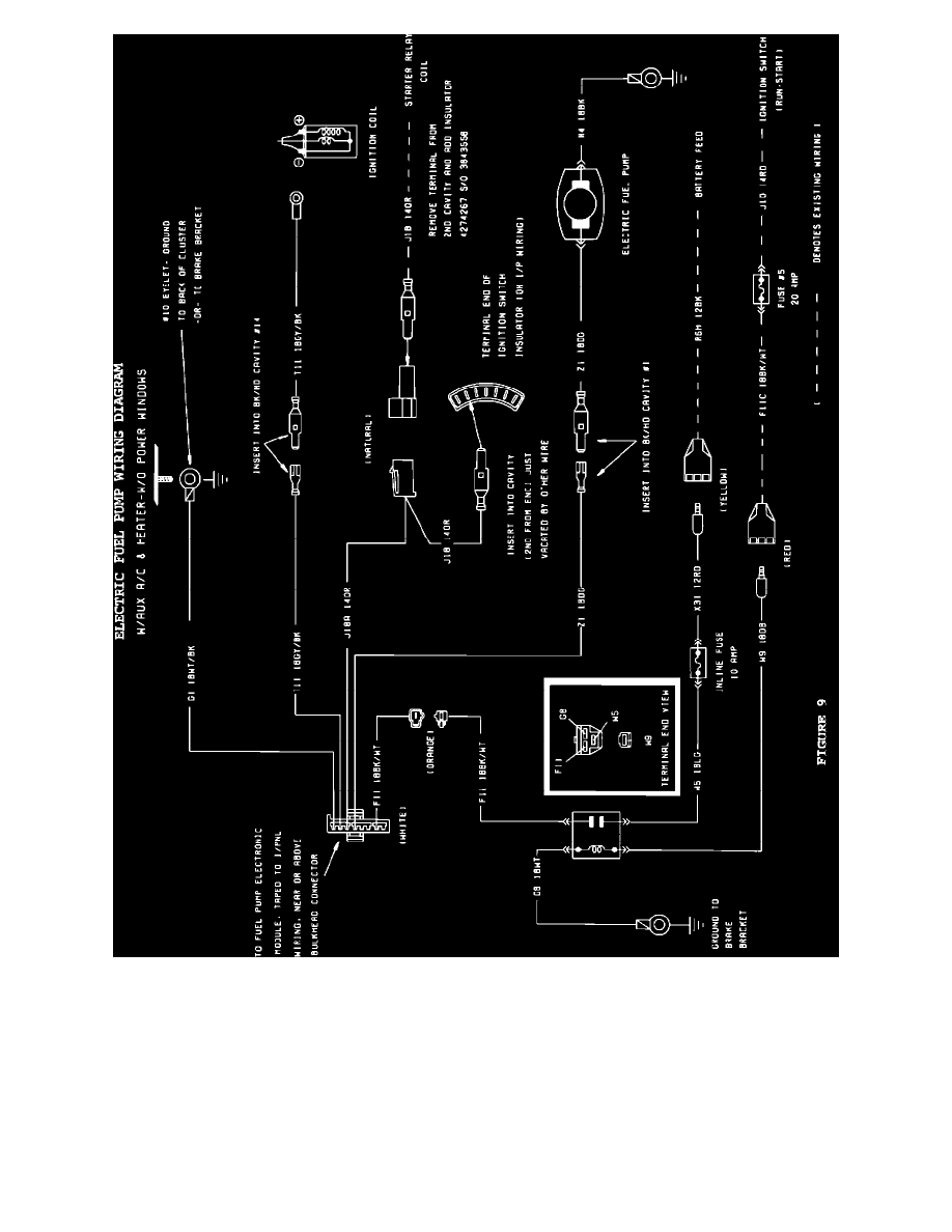
FIGURE 9 - ELECTRIC FUEL PUMP WIRING DIAGRAMW/AUX A/C & HEATER-W/O POWER WINDOWS
5.
For all vehicles except those which require a 78 amp alternator package:
Reinstall instrument panel side, then engine compartment side of bulkhead connector and torque bolt to 40 inch pounds.
NOTE:
REFER TO FIGURES 7, 8, OR 9 FOR OVERALL WIRING DIAGRAMS.
E.Engine Compartment Fuel Reservoir/Filter Lnstallation