
PB 150 V8-318 5.2L VIN T 2-BBL (1983)
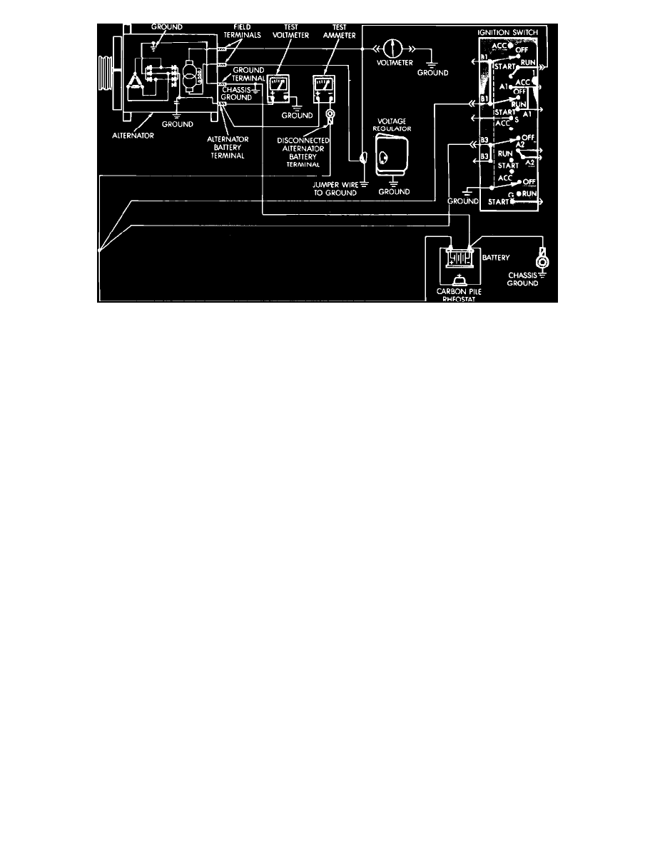
Fig. 2 Current output test (Typical)
TESTING
1.
Disconnect battery ground cable.
2.
Disconnect "Bat" lead at alternator output terminal.
3.
Connect a 0-150 amp D.C. ammeter in series between alternator "Bat" terminal and disconnected "Bat" lead wire.
4.
Connect positive lead of a suitable voltmeter to "Bat" terminal of alternator, then connect negative lead to a suitable ground.
5.
Disconnect voltage regulator wiring connector, then using suitable jumper wire, connect wiring connector green regulator field wire to a suitable
ground.
6.
Connect a suitable engine tachometer, then reconnect battery ground cable.
7.
Connect a variable carbon pile rheostat between battery terminals, ensuring carbon piles are in "open" or "off" position.
8.
Start engine and operate at idle speed, then adjust carbon pile and engine speed in increments until a speed of 1250 RPM at 15 volts is obtained on
all units except 1980-84 100, 114 and 117 amp units. On 1980-84 100, 114 and 117 amp units, adjust carbon pile and engine speed to 900 RPM at
13 volts. Do not allow voltmeter range to exceed 16 volts during testing.
TEST RESULTS
1.
Note ammeter reading. Ammeter reading should be within specified limits noted in specification charts in individual truck chapters.
2.
If reading is less than specified, alternator is defective.
3.
After completion of current output test, turn off carbon pile and ignition switch, then disconnect battery ground cable.
4.
Remove ammeter, voltmeter, tachometer and carbon pile, then reconnect "Bat" lead to alternator output terminal.
5.
Disconnect jumper wire from ground, then reconnect voltage regulator wiring connector.
6.
Connect battery ground cable.
Alternator & Regulator Diagnosis