
PB 150 V8-318 5.2L VIN T 2-BBL (1983)
Voltage Regulator: Testing and Inspection
Mitsubishi Alternators
Voltage Regulator Test
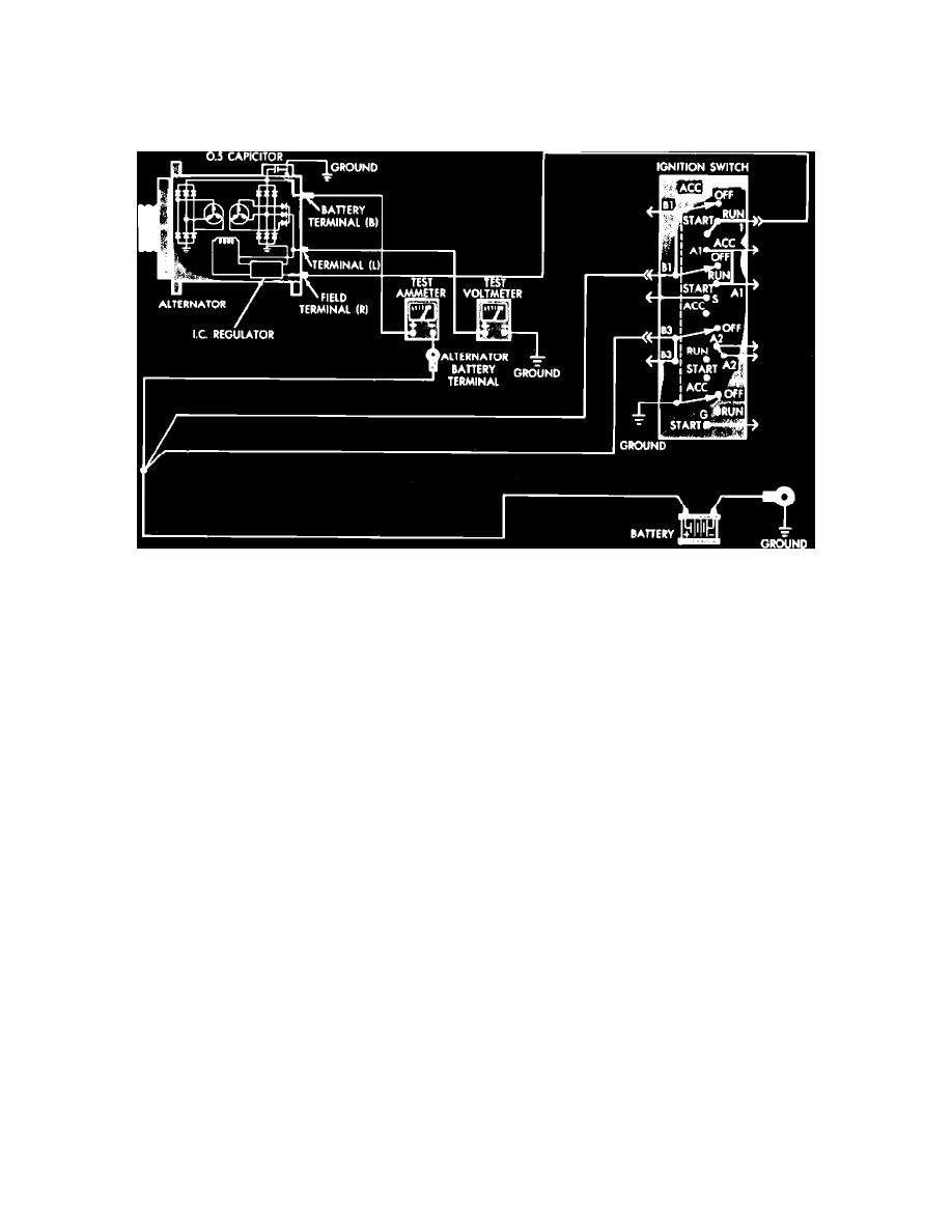
Fig. 2 Voltage regulator test connections
1.
With ignition switch in Off position, disconnect alternator battery lead at output terminal and connect ammeter in series between alternator and
disconnected lead.
2.
Connect a voltmeter between alternator L terminal and ground. Voltmeter should indicate zero voltage. If voltage is present, the alternator or
charging system wiring is defective.
3.
Place ignition switch in the On position and note voltmeter reading. Voltmeter reading should be 1 volt or less. If a higher reading is indicated, the
alternator is defective.
4.
Connect a tachometer to engine, then start and operate engine at approximately 2000 to 3000 RPM and note ammeter reading. When starting
engine, ensure no starting current is applied to ammeter.
5.
If ammeter reading is 5 amps or less on 1981-83 units, or 10 amps or less on 1984-86 models, check voltmeter reading with engine operating at
2000 to 3000 RPM. The charging voltage should be 14.4 volts at 68° F.
6.
If ammeter reading is above 5 amps on 1981-83 models or above 10 amps on 1984-87 models, continue to charge battery until reading drops to
less than 5 amps on 1981-83 models, or to less than 10 amps on 1984-87 models. If voltage is not within limits, alternator is defective. An
alternative method to limiting charging current is to connect a {1/4} ohm (25 watt) resistor in series with battery.
Alternator & Electronic Voltage Regulator Diagnosis