
PB 150 V8-318 5.2L VIN T 2-BBL (1983)
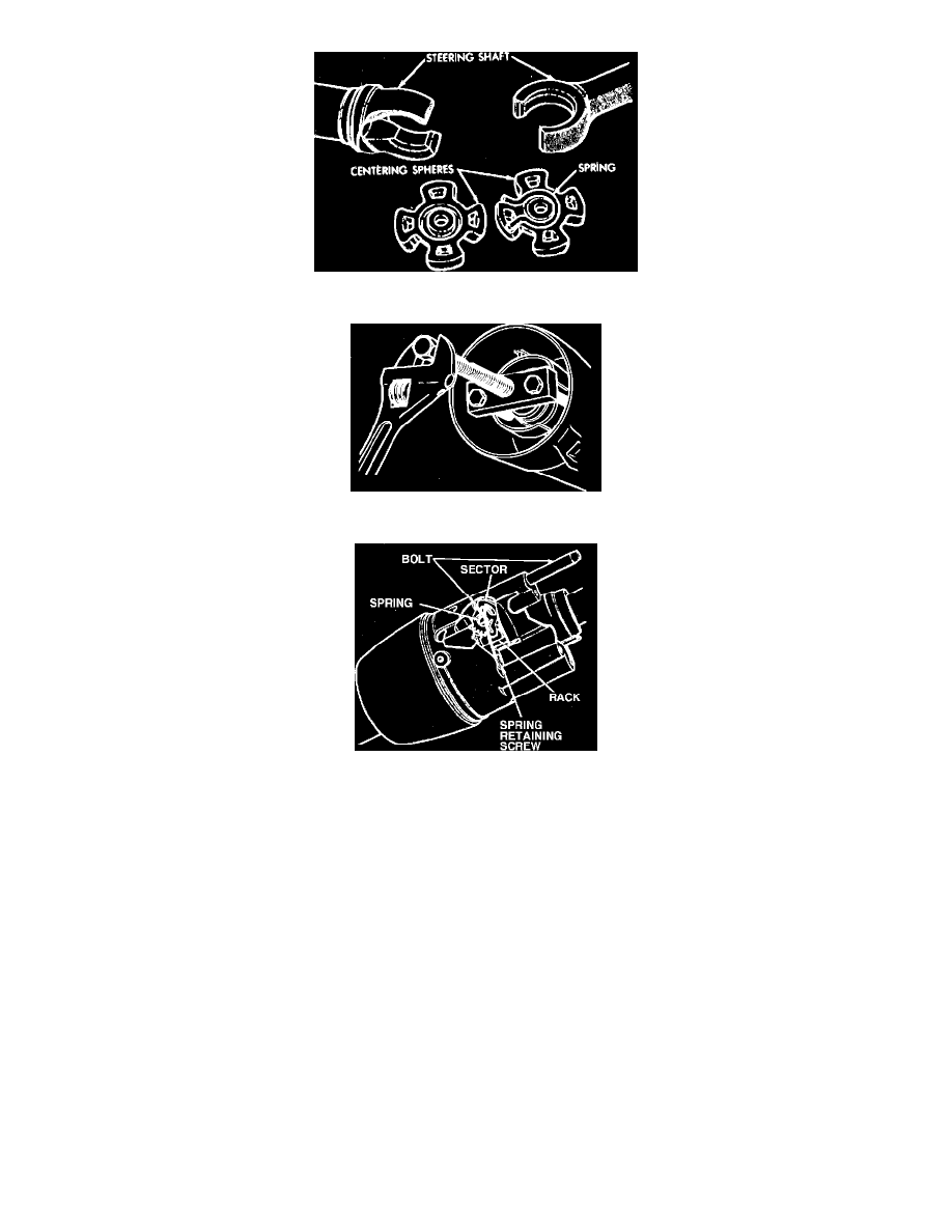
Fig. 24 Steering shaft centering spheres & anti-lash spring
Fig. 25 Shift tube removal. Except front wheel drive
Fig. 26 Sector & bolt spring assembly
19. Remove steering shaft assembly through upper end of column.
20. Disassemble steering shaft assembly by removing center spheres and anti-lash springs.
21. Remove the 4 support to lock plate retaining screws and remove support from end of column and jacket. If necessary, remove the 2 retaining
screws and shift gate from support.
22. Remove shift tube retaining ring using a screwdriver, then remove thrust washer. On floor mounted gearshift lever assemblies, it will be
noticed that there is no shift tube after the support is removed from the steering column jacket. The lock system actuator and spring can
be lifted from the top end portion of the steering column jacket.
23. Using tool C-4120 or equivalent and bushing, remove shift tube from bowl. Do not hammer or pull on lower or upper shift tube as plastic
joint may be sheared.
24. Remove shift tube from jacket through lower end.
25. Remove lock plate by sliding out of jacket notches and tipping down toward bowl hub at a 12 o'clock position and under jacket opening, then
remove wave washer.
26. Remove bowl from jacket, then remove shift lever from bowl by winding spring up with pliers and pulling out.
27. Remove tilt lever opening shield from bearing housing.
28. Remove lock bolt spring by removing spring retaining screw and moving spring clockwise to remove from bolt.
29. Remove snap ring from sector drive shaft, then using a hammer and punch, lightly tap drive shaft from sector. Remove drive shaft, sector, bolt,
rack and spring (also shim if used).
30. Drive out tilt release lever pin, then remove lever and release spring. To relieve load on release lever, hold shoes inward and wedge block between
top of shoes (over slots) and bearing housing.
31. Remove lock shoe pin, then remove lock shoes and springs.
32. Remove bearings from housing only if they are to be replaced. Remove separator and balls from bearing. Place housing on a flat surface, then with
a pointed punch against the back surface of race, carefully drive out race until a puller can be used. Repeat for other race.