
PB 150 V8-318 5.2L VIN T 2-BBL (1983)
3. Pull body off shaft and shoe assembly.
INSPECTION
1. Clean all parts in suitable solvent then inspect for wear or damage.
2. Inspect condition of shift lever gate and inner end of shift lever.
3. Inspect turn signal switch for distortion, broken or damaged parts.
4. Inspect steering shaft bearings for smooth operation. Replace bearing if it is rough or worn.
ASSEMBLY
During assembly, apply a thin coat of NLGI grade E.P. 2 or equivalent grease to all friction surfaces.
1. Clamp column in a vise so that both ends are accessible.
2. Check column tube-to-mandrel rivets for tightness. If loose, replace using 1/8 inch diameter by 1/4 inch long (1/8 inch grip) rivets. When
replacing rivets, make sure to use ones of the same type material as removed.
3. Install floor plate and grommet on lower end of column jacket.
4. On automatic transmission columns:
a. Place gearshift housing on column jacket, then with dust seal and shift tube support installed on shift tube, slide assembly into jacket. Guide
key on upper end of tube into slot in gearshift housing.
b. Position crossover load spring and shift lever in gearshift housing and tap the pivot pin into place.
c. Install shift lever gate on lock housing.
d. If used, feed gear selector dial lamp wire through hole behind transmission dial on lock housing and route wire down through space between
housing and jacket. Secure lamp assembly to rear of dial with 2 screws and install lens.
e. With shift lever in mid-position, seat lock housing on top of jacket, indexing key in housing with slot in jacket. Install and alternately tighten
all 4 screws to insure proper seating of housing, then torque to 90 inch lbs.
f.
Install indicator bracket.
5. Grease and assemble the two lock levers, lock lever spring and pin, then install assembly in housing. Seat pin firmly into bottom of slots, making
sure that lock lever spring leg is firmly in place in lock casting notch.
6. Install lock lever guide plate and retaining screws.
7. Position ignition switch to center detent (Off) position and shift lever in Park (Reverse for manual transmission columns). Feed wires down
through space between housing and jacket, then position switch in housing and tighten the 3 retaining screws.
8. To install ignition lock, turn ignition lock to "Lock" position and remove key. The cylinder will move inward and a spring loaded retainer will
snap into place, locking the cylinder to the housing.
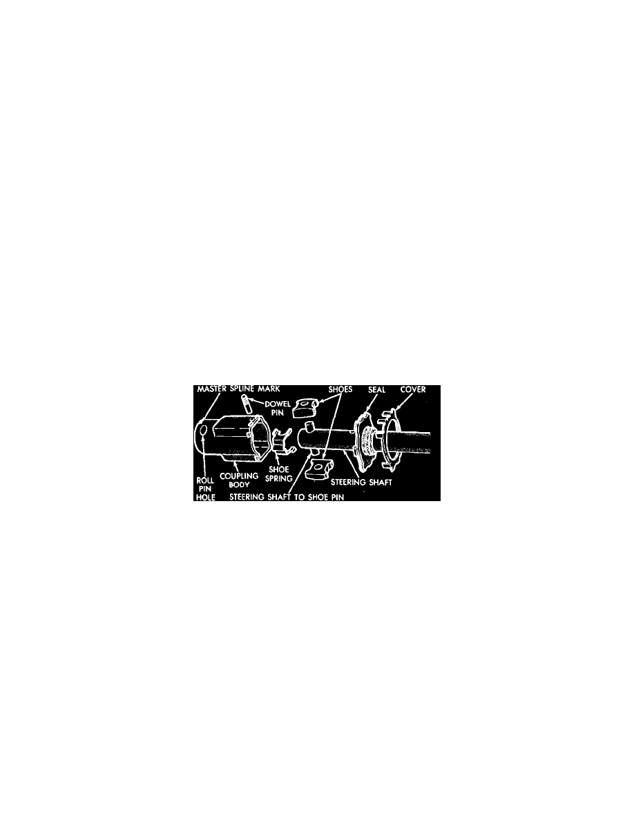
Fig. 14 Steering shaft pot coupling exploded view
9. To assemble steering shaft "Pot" coupling:
a. Fill coupling body about 1/2 full with NLGI grade 2 E.P. or equivalent grease.
b. Place cover and seal on shaft.
c. Press shoe pin into steering shaft so that it projects an equal mount on each side of shaft.
d. Place spring on side of shaft and over the shoe pin, then place shoes on pin ends with flat side toward spring, engaging tangs.
e. Squeeze shoes together to compress spring and push assembly into coupling. Align master spline mark of coupling body with master spline on
upper shaft.
f.
Drive in a new roll pin until flush with outer surface of coupling body.
g. Position seal and cover on body and crimp cover tangs securely over projections on body.
h. Move shaft in and out several times to distribute lubricant.
10. Install bearing support (floor shift), bearing and spring on steering shaft and insert the steering shaft assembly into the column.
11. Install steering column shaft lock plate sleeve over shaft lock plate pin. Do not hammer column shaft lock plate sleeve, as damage to the
telescoping shaft may result.
12. Install coil spring or bearing lower snap ring.
13. Install ignition key lamp assembly into bearing housing.
14. Place rubber insulator with grounding staple over column upper bearing and install assembly into bearing housing bore. Use lubricant to ease
installation.
15. Install turn signal switch into bearing housing, while feeding the wires through opening in housing. Also feed the ignition key lamp wires through
the opening.
16. Install retaining plate over the switch and torque the retaining screws to 27 - 30 inch lbs.
17. Install turn signal lever. If equipped with speed control, feed wires through opening provided in the bearing housing.
18. Place bearing housing assembly on steering shaft, while feeding the wires through the opening between lower housings and jacket.