
PB 150 V8-318 5.2L VIN T 2-BBL (1983)
Steering Gear: Description and Operation
Manual Steering Gear
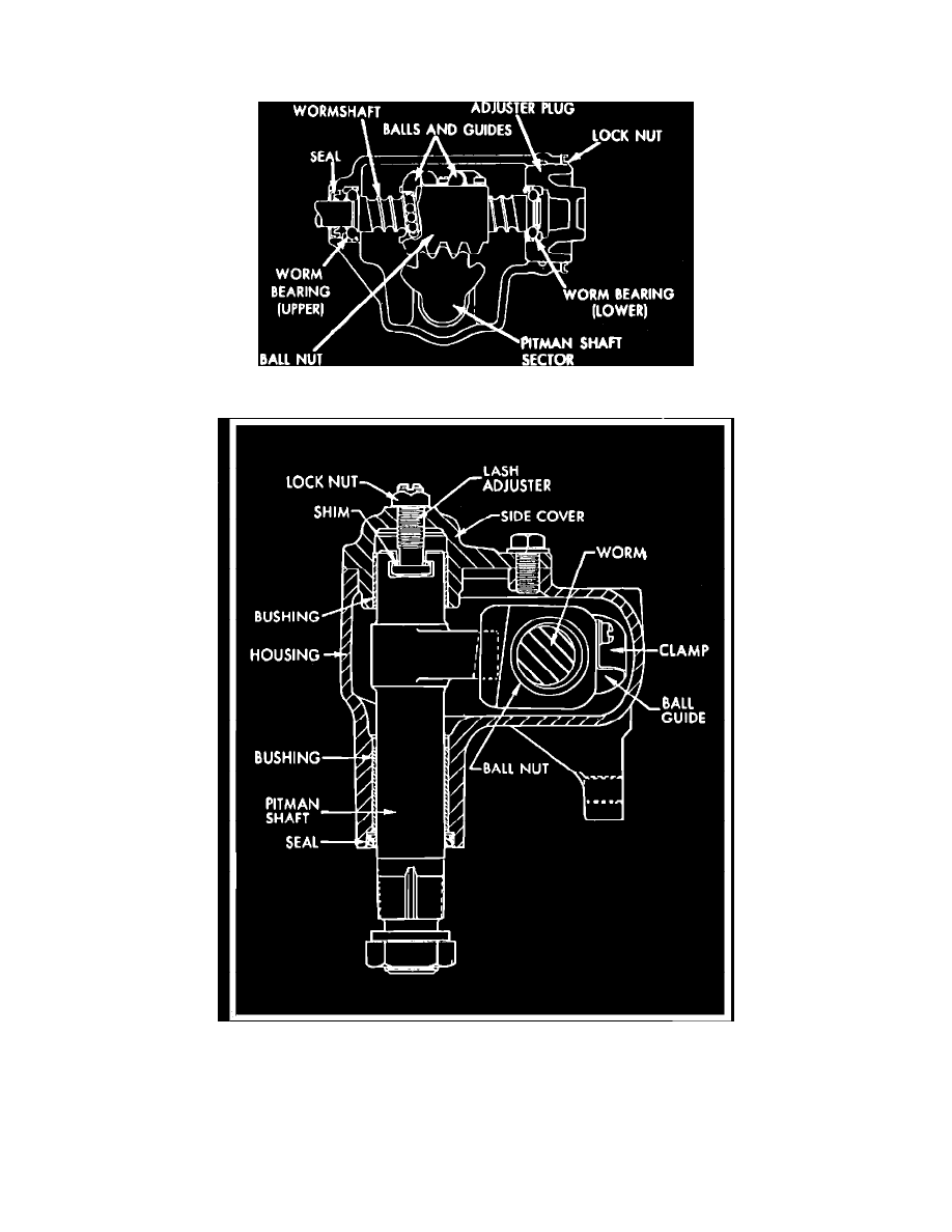
Fig. 1 Sectional view of Saginaw recirculating ball-worm & nut steering gear
Fig. 2 Cross-sectional view of Saginaw recirculating ball-worm & nut gear
As shown, the wormshaft on the lower end of the steering shaft and the ball nut which is mounted on the worm have mating spiral grooves in which
steel balls circulate to provide a low friction drive between wormshaft and ball nut.
Two sets of balls are used, ranging in number from approximately 20 to 30 to a set, depending upon the size of the gear unit. Each set of balls operate
independently of the other. The circuit through which each set of balls circulates includes the grooves in the worm and ball nut and a ball return guide
attached to the outer surface of the nut.
When the wheel and steering shaft turn to the left, the ball nut is moved downward by the balls which roll between the worm and nut. As the balls